Building a Division 2 sailboard
By Malcolm Jones
Background information
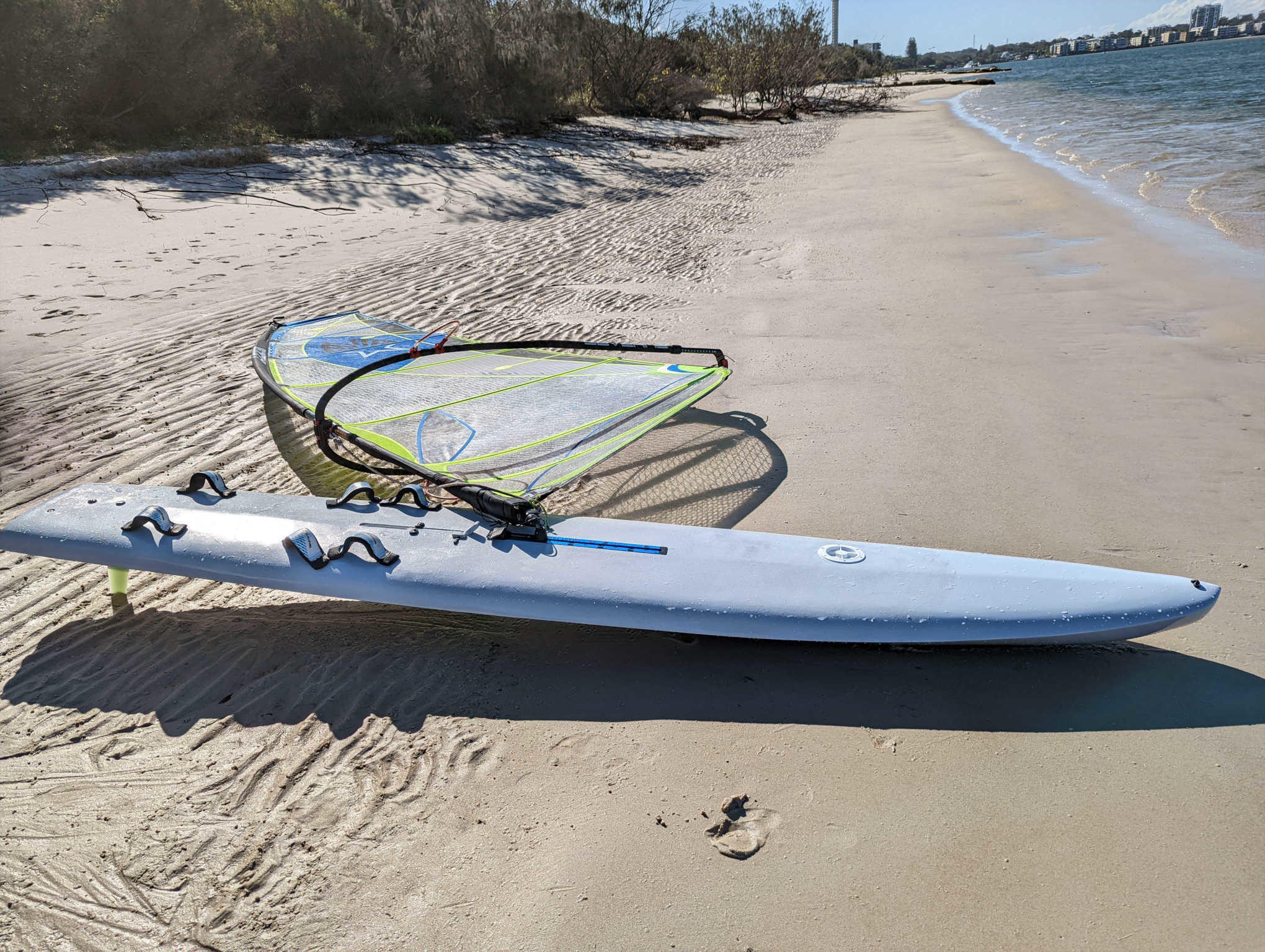
This guide documents the process of building a division-2 Lechner-A390 sailboard which was the Olympic class board used for the 1988 and 1992 games.
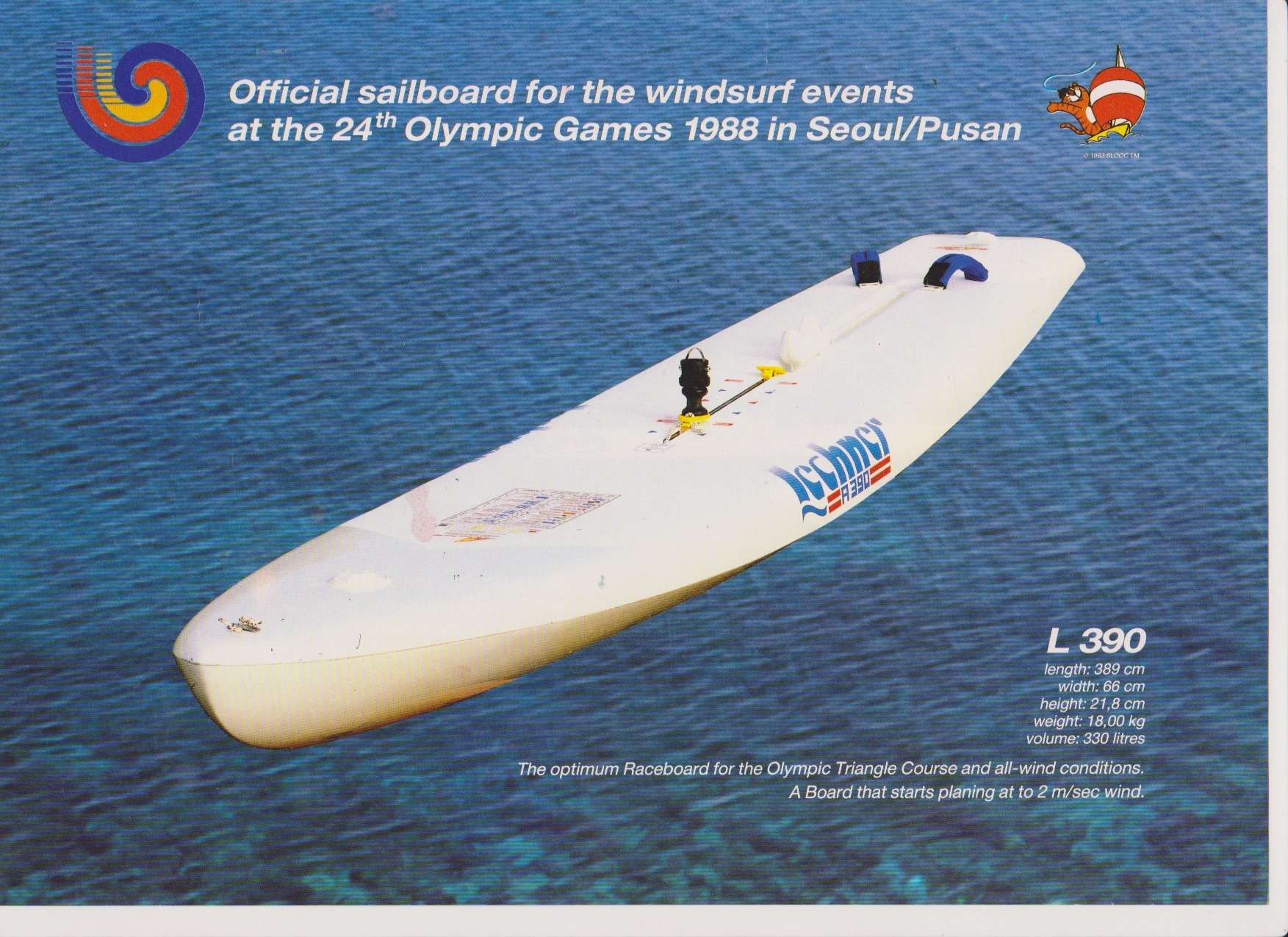
Overall dimensions of the Lechner are shown in Figure 1. There are slight differences between the 1988 and 1992 versions with the later design having the mastrack and centre-board further aft. Otherwise from what I can tell the hull forms were identical.
Summary of build process
The board was constructed using a skin on frame technique. The skin is a carbon-fibre-foam sandwich and the frame is a combination of either carbon- or glass-foam-sandwich panels. This method eliminates the solid internal foam core typically used in windsurfers. The result is a hollow board which I think has certain advantages compared to a foam cored board.
The original Lechner-A390 board was also a hollow board. However, I did not have access to the original design plans nor any knowledge on the method used to construct the original Lechner-A390 boards. The following is therefore just one approach which suited a one-off build.
Build a positive mould
Vacuum bag the deck over the mould; then demould
Vacuum bag the hull over the mould; then demould
Vacuum bag chine brackets over the mould; then demould
Build the internal frame composite sandwich panels
Build the centreboard case
Build the finbox case
Build the masttrack case
Glue the internal frame to the hull
Glue the chine brackets to the hull
Glue the deck to the hull
Fill and fair outer HDF
Vacuum bag on the hull outer lamination
Vacuum bag on the deck outer lamination
Post cure board at \(55^\circ\)C for 16 hours
Fill and fair the lamination
Build centreboard
Paint the board
Board design
Lechner A-390 CAD model
The board is based on a division-2 Lechner-A390 design. Available for download on a Facebook Division II group is a computer-aided design (CAD) model of the board. The CAD model provides the outer mould line geometry only and does not include details on the internal structure, masttrack, centre-board-box or finbox placements. According to the Facebook post the CAD model was derived from reverse engineering an existing board. I cannot say how accurately the CAD model represents a Lechner as I did not have access to the original design plans nor an actual Lechner board for comparison.
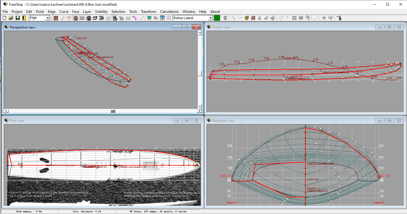
The CAD model is in “Freeship” format and version 3 of Freeship software was required to read the file. Freeship is Windows only software and does not appear to be actively developed anymore. I was able to install Freeship and open the file, as shown in Figure 2. Essentially the only data I needed to extract from this file was the centre-line profile and cross-section profiles. With these profiles I could then build the frame for the mould and the internal frame for the actual board.
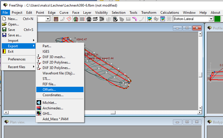
I found that using the File:Export:Offsets function produced a single output text file with coordinates defining the following 2-dimensional profiles:
stations (vertical slices across the board)
buttocks (vertical slices along the board)
waterlines (horizontal slices)
The LechnerA390-6.fbm file had defined the above offsets at various locations. Using the Freeship tool calculate:intersections it was possible to edit the offset locations (either adding or deleting) and then export them to a text file. When building the mould I used \(150\,\)mm spacing between stations. I also needed to define a buttock corresponding to the centre-line profile. After defining these intersections I exported the coordinates to a text file. The exported coordinates were collated into 3 Excel workbooks:
The centre-line profile (buttock at \(y=0\)) is shown in Figure 3. The board width is also shown in Figure 3 and this was determined by calculating the width of the board at a given station. Note the board width does not correspond to a particular waterline but instead is a projection of the board width onto the \(x-y\) plane. In fact the waterline data was not actually needed but is included in above Excel files for completeness.
Plots of some station profiles are shown in Figure 4 or for interactive version of this plot, which includes all stations, see Stations.html. I was also able to export the Freeship model as a 3D surface mesh (STL format) and render it using FreeCad software and images of the 3D model are shown in Figure 5.


Location of fittings
The position of the fin-box, centre-board and mast-track are given in Table 2. I determined these locations myself but as a guide referred to photos of the Lechner-A390 design and other raceboards. There is also some useful data from someone who owns a Lechner-A390 in this www.seabreeze.com.au post. In Table 1 the measurements are taken from the most aft location on either the deck or hull, depending on the feature being measured. As seen in the centre-line profile of Figure 3 the stern of the board slopes forward. As a result the aft point of the deck is \(80\,\)mm forward of the aft point of the hull.
| Feature | mm | origin |
| Fin bolt back | 170 | deck |
| Fin bolt front | 280 | deck |
| Fin slot back | 223 | hull |
| Fin slot front | 378 | hull |
| Centre hull slot back | 581 | hull |
| Centre hull slot front | 1451 | hull |
| Centre board pivot | 1350 | deck |
| Centre deck slot back | 1155 | deck |
| Centre deck slot front | 1540 | deck |
| Back glide assembly | 1600 | deck |
| Front glide assembly | 2200 | deck |
Summary of composite layup
The general layup schedule is given in Table 2. In general, only one layer of cloth was laminated to each side of the sandwich. However, for high load areas such as centre-box, fin-box and mast track extra layers were used. The sandwich core was high density foam (HDF) with a density of either 65 or 85 kg/m\(^3\) and the resin was epoxy.
Target design weight
The original Lechner-A390 board had a quoted weight of \(18\,\)kg, Figure 1. The Division 2 class rules specify minimum board weights of \(18\,\)kg (category A & B) and \(16\,\)kg (category C). These weights exclude the centre-board and footstraps but include the fin. The different categories relate to the size and type of sail allowed. Category C corresponds to updated rules introduced in 2015 which allowed sails up to \(9.5\,\)m\(^2\). So it looks like the original Lechner-A390 was built to the class minimum weight of \(18\,\)kg that existed when they were build.
Using the layup given in Table 1, along with estimates of component weights (finbox, centre-box etc.) I estimated a weight of 15-16\(\,\)kg could be achieved. The as-built board ended up being \(16.9\,\)kg so more than I’d hoped for but still less than the original Lechner-A390 board. For comparison the division 2 boards built by One Hundred Boardz range between 15-16\(\,\)kg and these are using a polystyrene core. A full break-down of the board weight is given in Section Board weight.
| Component | Core thickness mm |
Core density kg/m3 |
Fibre type | Fibre weight g/m2 |
| Deck | 5 | 85 | Plain weave carbon | 200 |
| Hull | 5 | 85 | Double Bias Carbon | 150 |
| Frames (high loads) | 10 | 65 | Double Bias Carbon | 150 |
| Frames (low loads) | 10 | 65 | Plain Weave E-Glass | 86 |
Building the mould
The mould was constructed using a skin on frame technique using \(3\,\)mm thick medium-density fibreboard (MDF) as the material. Further coatings of plaster and fibreglass were then applied to get a faired surface.
Transformation of CAD to mould templates
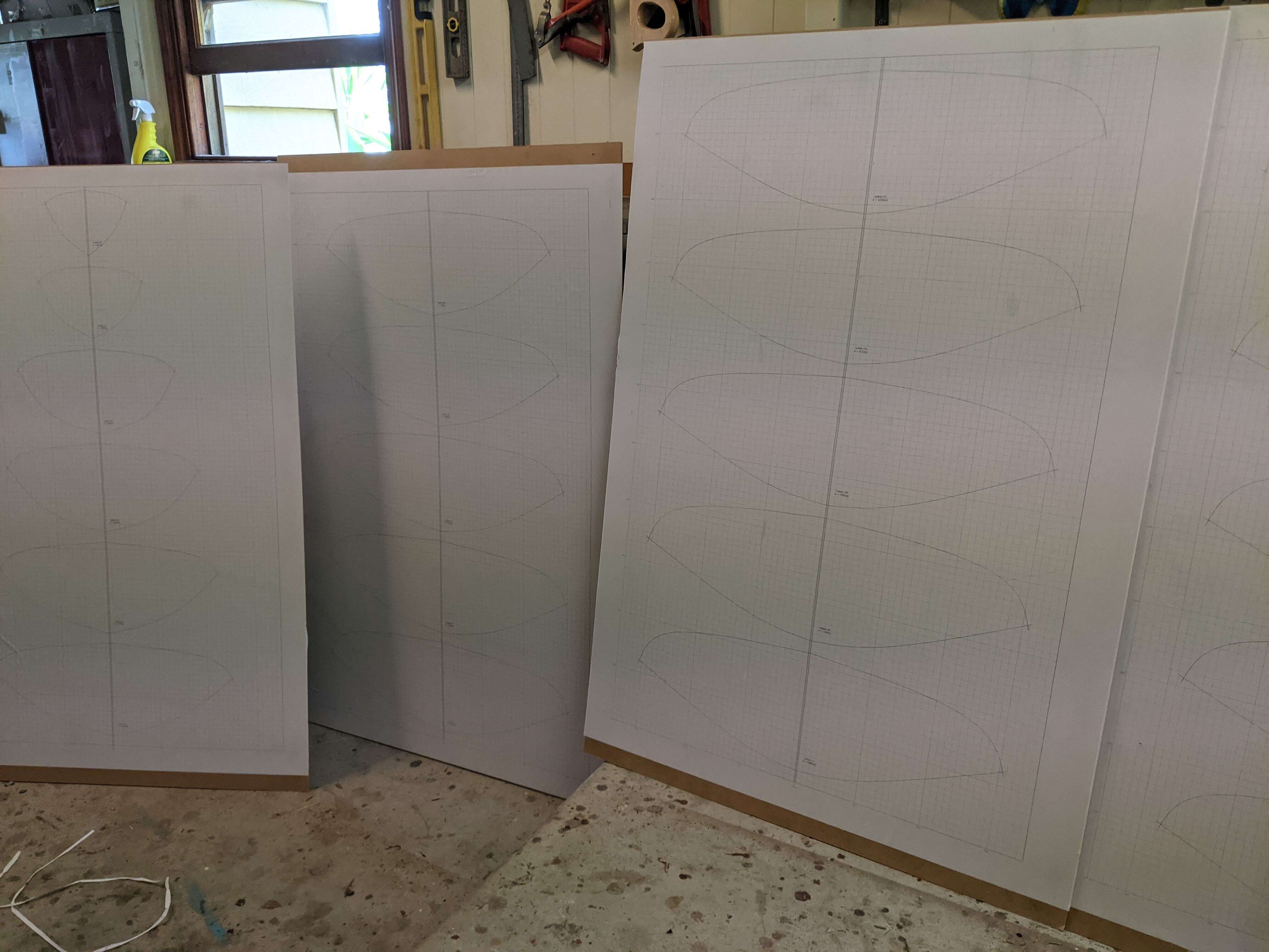
The first step was to offset the centre-line profile and station profiles (Figures 3 and 4) by the thickness of the mould plus the thickness of the board skin. The profiles were then printed on A0 paper and the pdf files can be downloaded from these links:
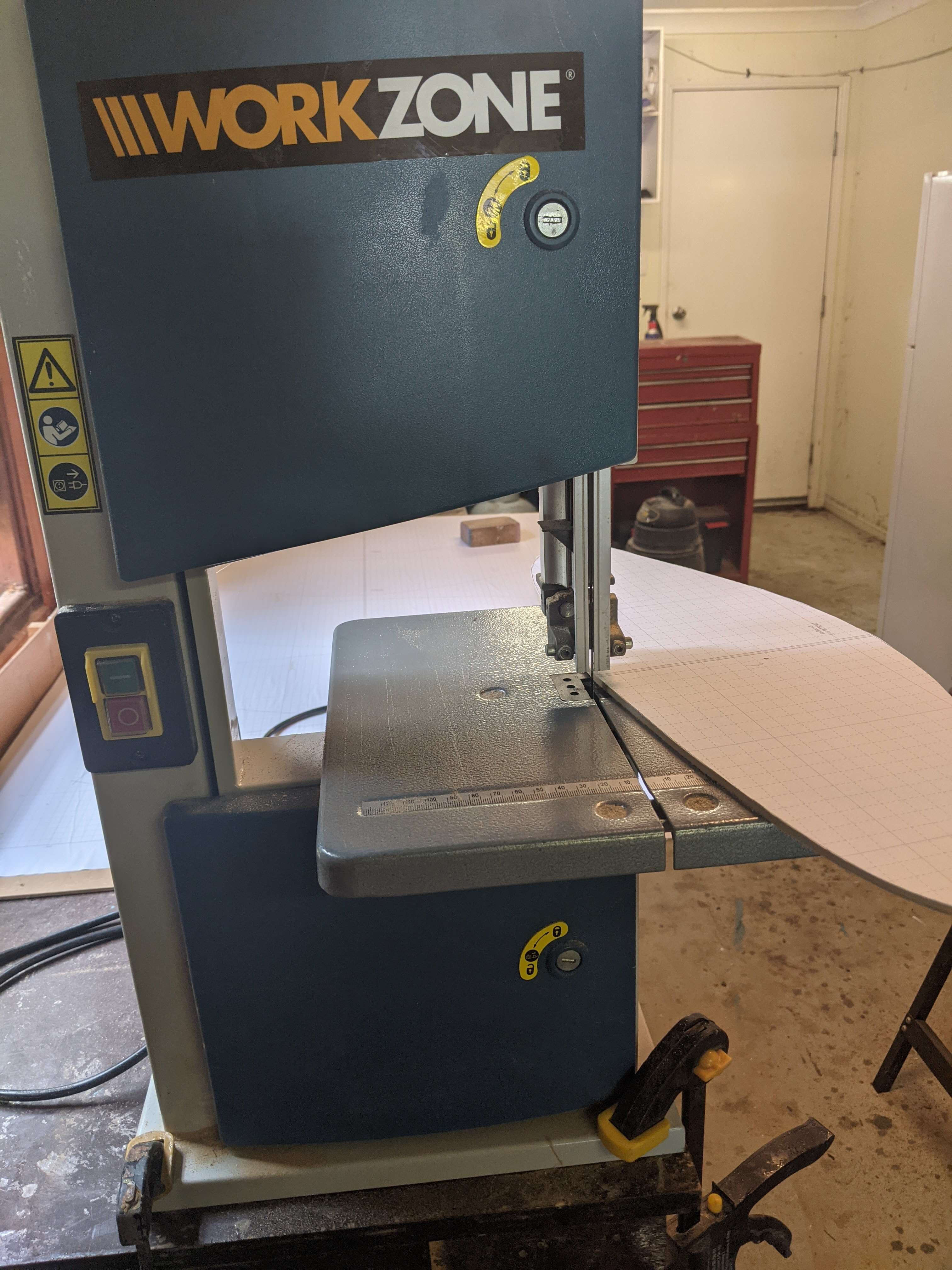
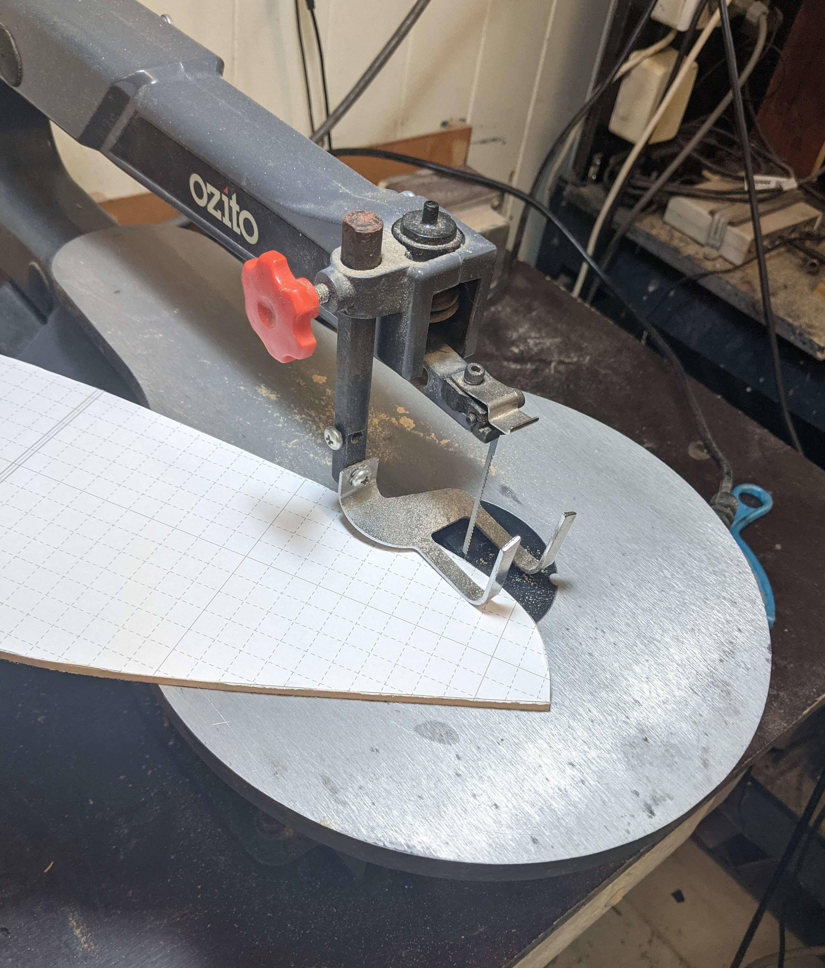
MDF templates
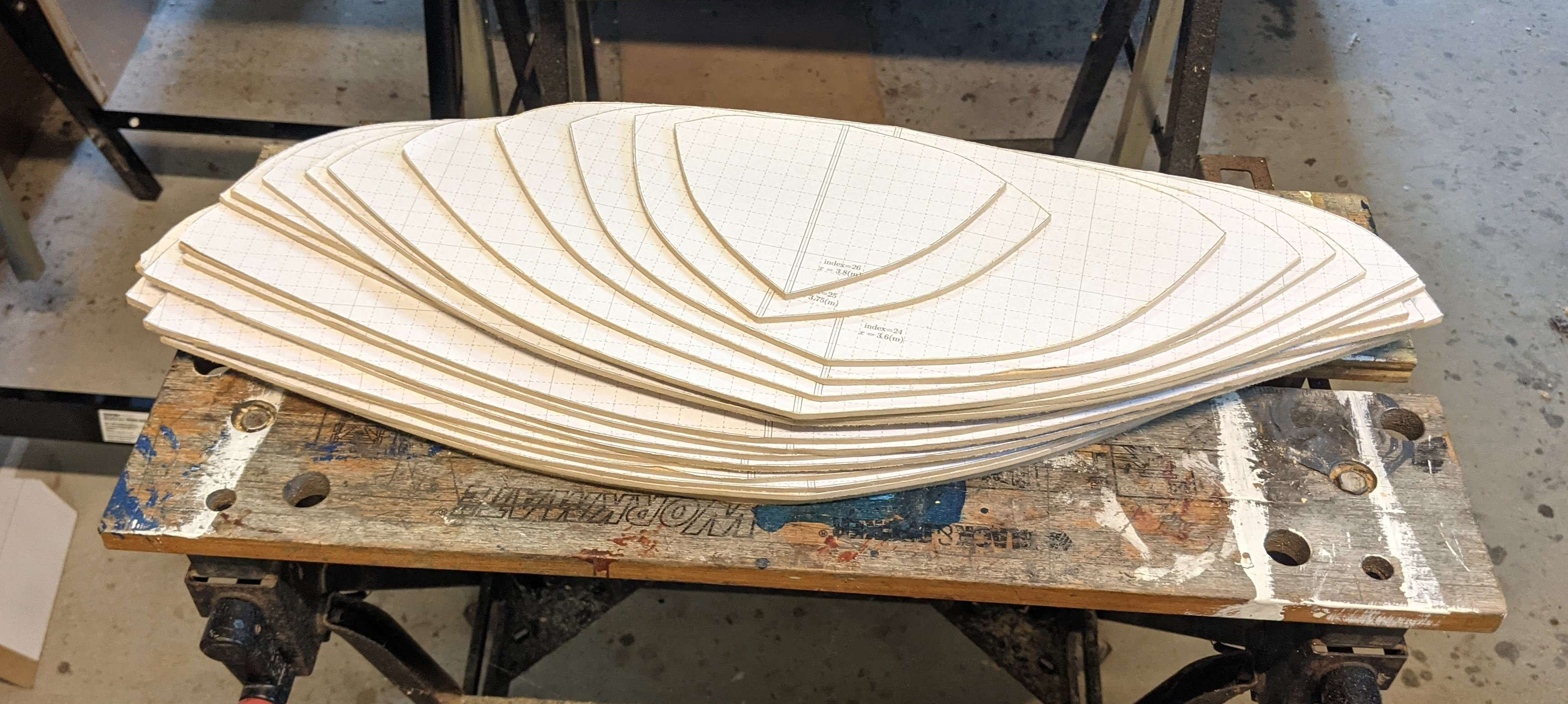
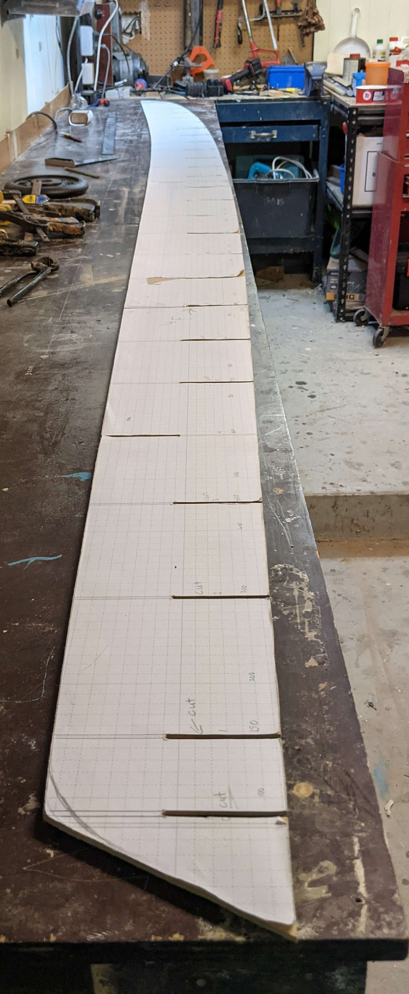
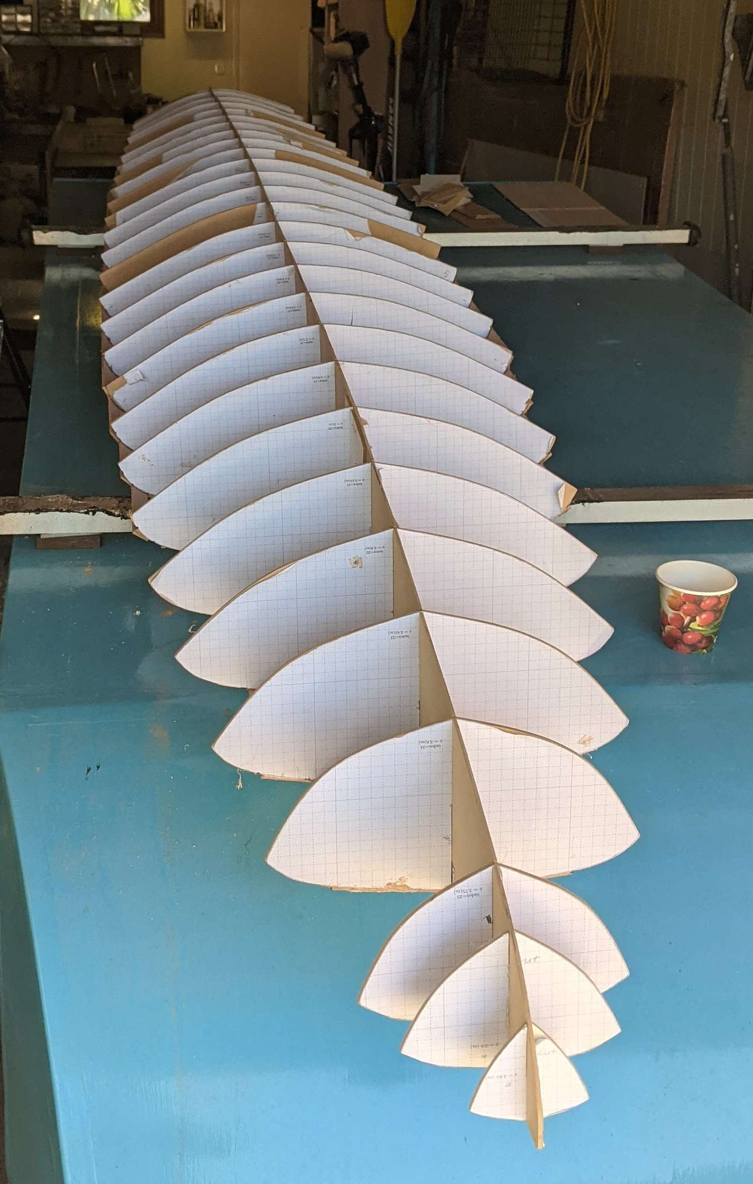
The A0 printout were glued to \(3\,\)mm thick MDF sheets, Figure 6. Using either a bandsaw or a scroll saw the templates were cut out, Figure 7. There were a total of 28 station profiles, Figure 8, and the location of the stations is given in Table 3.
The centre-line profile is shown in Figure 9 and was also cut from \(3\,\)mm thick MDF. Since the MDF sheets were \(2.4\,\)m long the centre-line profile had to be cut in two parts and then joined.
| Index | x (m) | Index | x (m) | |
| stern | 0.00 | 14 | 2.10 | |
| 0 | 0.08 | 15 | 2.25 | |
| 1 | 0.15 | 16 | 2.40 | |
| 2 | 0.30 | 17 | 2.55 | |
| 3 | 0.45 | 18 | 2.70 | |
| 4 | 0.60 | 19 | 2.85 | |
| 5 | 0.75 | 20 | 3.00 | |
| 6 | 0.90 | 21 | 3.15 | |
| 7 | 1.05 | 22 | 3.30 | |
| 8 | 1.20 | 23 | 3.45 | |
| 9 | 1.35 | 24 | 3.60 | |
| 10 | 1.50 | 25 | 3.75 | |
| 11 | 1.65 | 26 | 3.80 | |
| 12 | 1.80 | 27 | 3.85 | |
| 13 | 1.95 |
Assembling the mould frame
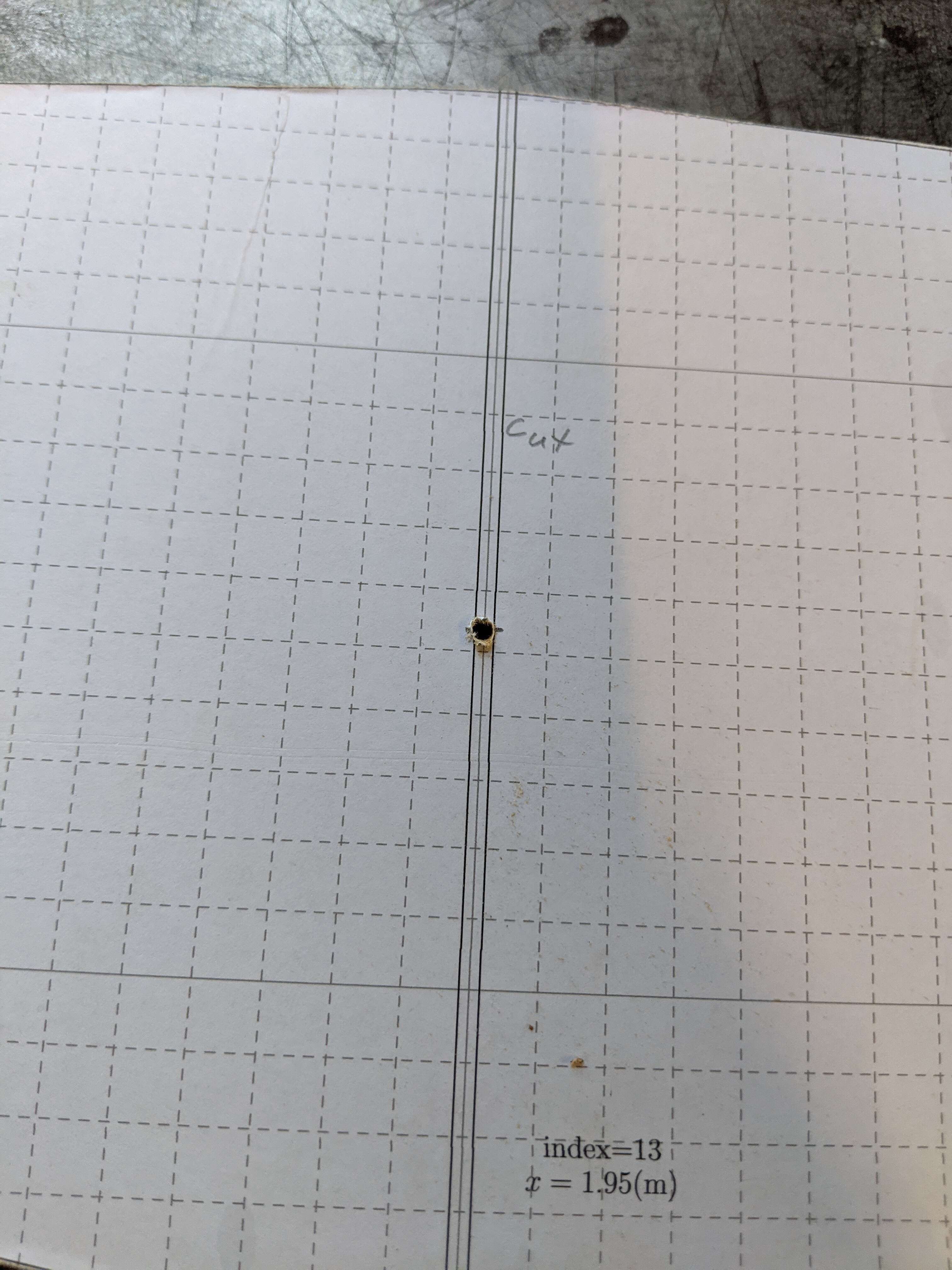
The frame profiles had \(3\,\)mm slots cut into them to allow mating of the stations with the centreline. The position of the slot was marked on the A0 templates as shown in Figure 10. The length of the slot cut was half of the station height. The slots on the centreline frame can be seen in Figure 9.
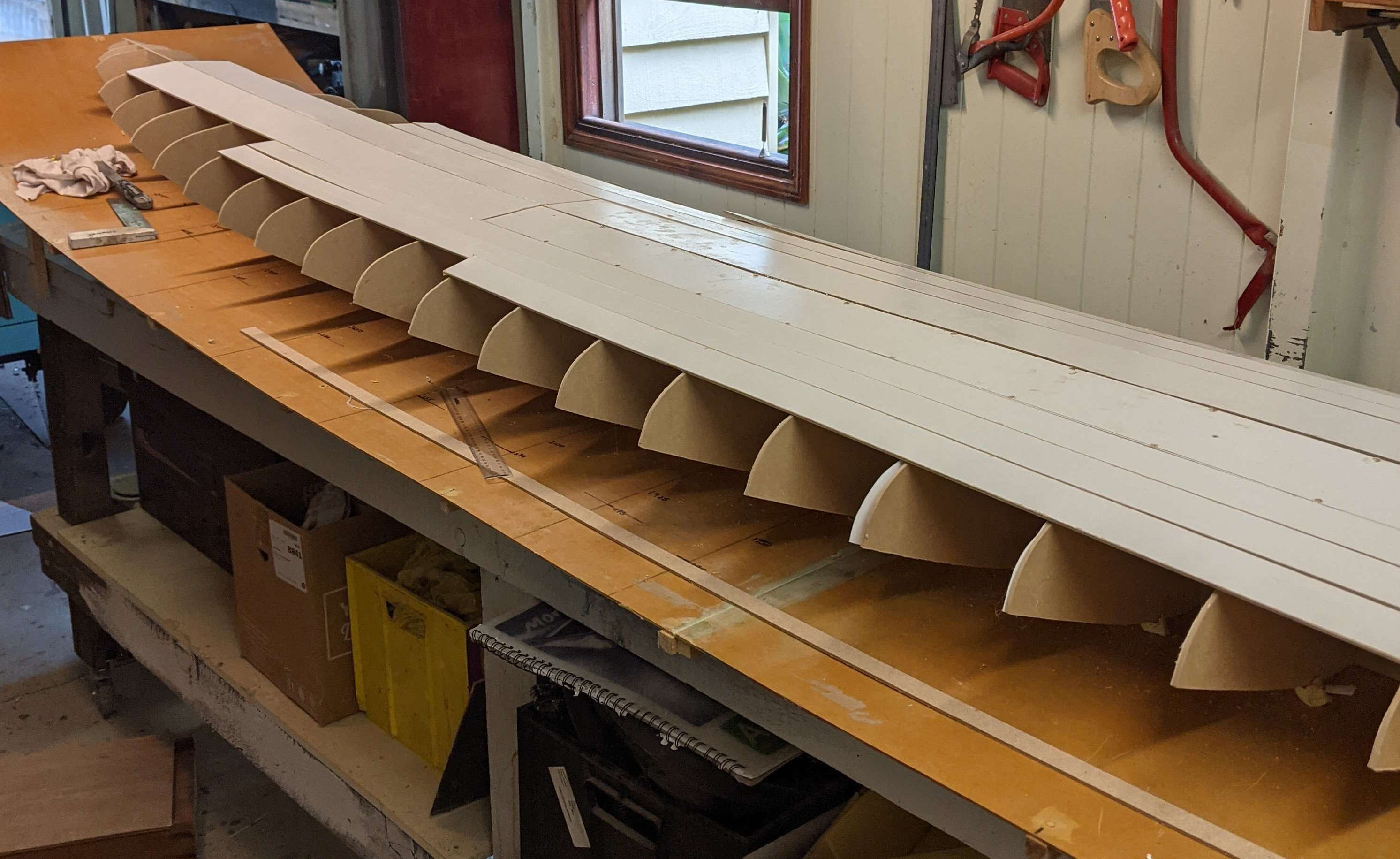
To assemble the mould frames a rocker table was setup. The rocker table is a sheet of \(3\,\)mm MDF, reinforced with spanwise struts. The rocker table was attached to a rigid workbench in such a way that it followed the profile of the centreline rocker. A centreline was marked on the rocker table to align the centreline frame. Similarly, lines were ruled on the rocker table at right angles to the centreline mark at each station location. These markings were used to ensure the frame was straight and square in planform sense.
The main challenge was ensuring the stations were square with the centreline when viewed end on (i.e. avoiding twist about the axial direction). Squareness in this direction relied, to a degree, on the accuracy of the slot cuts. The squareness was checked by measuring the normal distance from the rocker table to both the port and starboard chines of a given station and adjusting to ensure these two distances were equal. The stations were glued to the centreline using liquid nails. The rocker table with the assembled mould frame is shown in Figure 11.


Mould skin
A strip-planking method was used to cover the mould frame. The strips were cut from \(3\,\)mm MDF and the width varied depending on the curvature they had to follow. The strips were glued and nailed onto the frames.
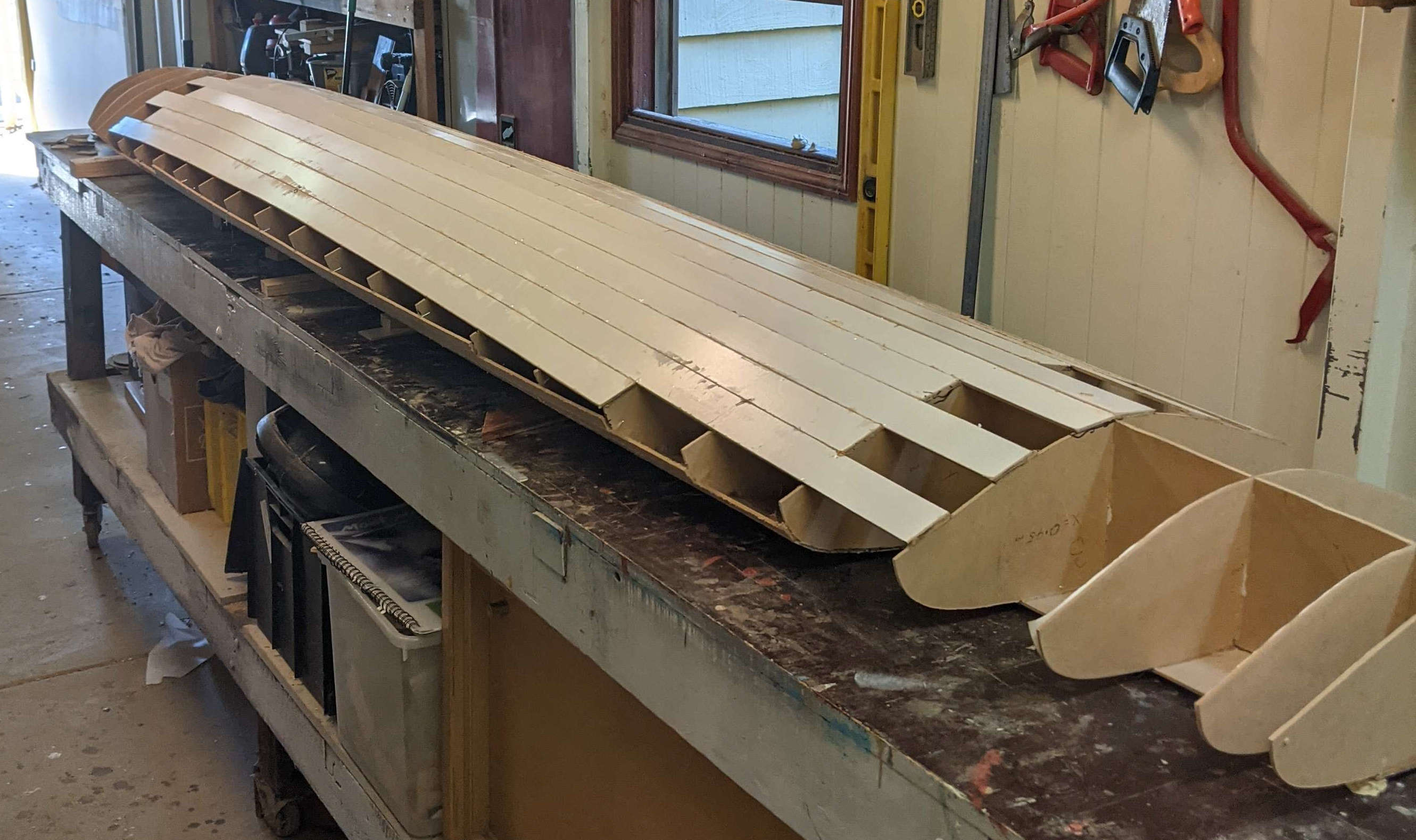
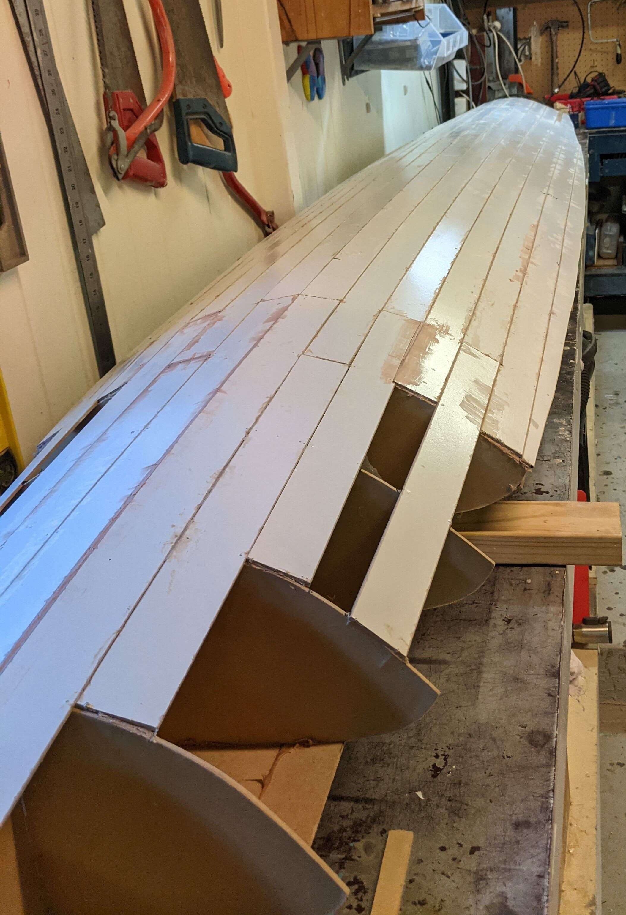
The deck skin was attached first and Figure 12 shows the initial build up of the strips. This initial deck skin tied the stations to the centreline and it was essential that the frame remained true during this phase. Figure 13 shows view from underside once these initial deck strips were attached.
Next the the hull skin was attached and this is shown in Figure 14 and Figure 15. Finally the gaps between the deck and hull skins were covered with narrower strips of MDF, individually cut to close the gap, Figure 16.
The final build up of the MDF strips is shown in Figure 17 and Figure 18. The curvature at the bow of the board was too tight to bend MDF around and instead the bow was build from foam, see Section Mould bow.
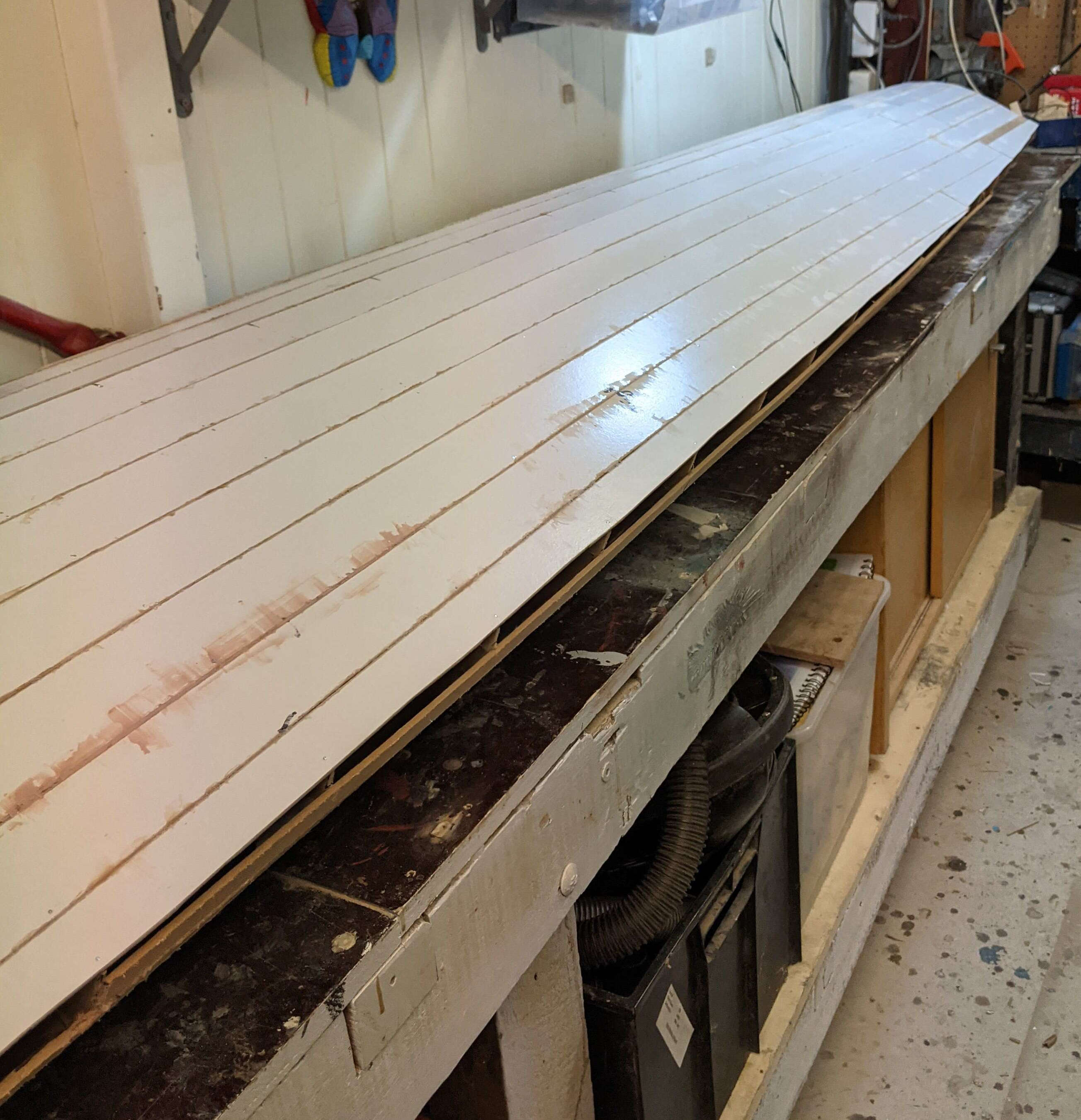


Filling and fairing the mould skin
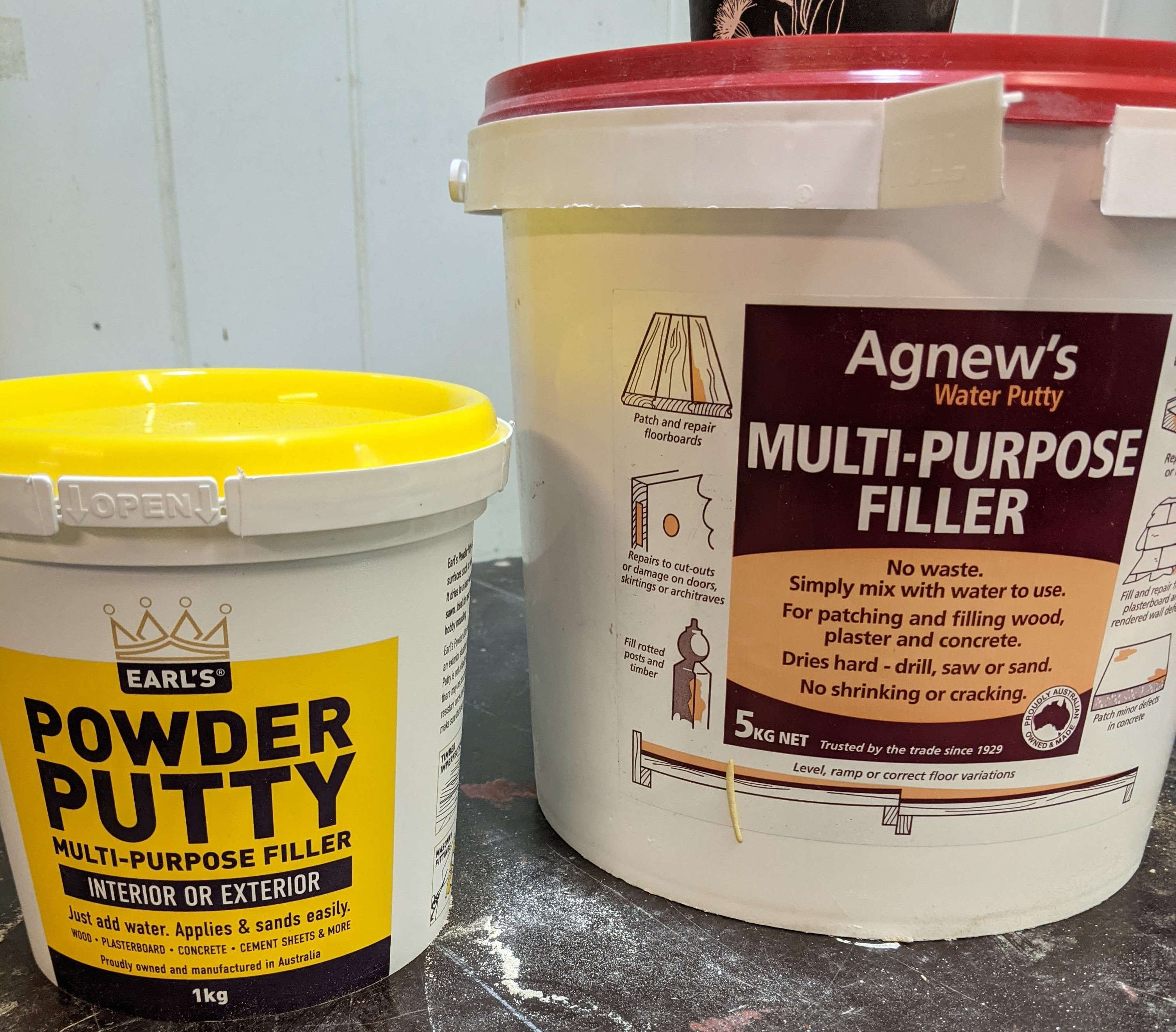
The MDF skin was roughly faired using a belt sander fitted with coarse sandpaper (80-grit or less). A plaster based filler (Figure 19) was then applied all over the surface. Using 80-grit with a hand-sanding block the plaster was faired. It was found the plaster clogged the sandpaper rather quickly, so I need to change the paper often. The process of filling with plaster and fairing was repeated a few times until I was happy with the overall shape and Figure 20.


Mould bow
Pieces of \(25\,\)mm thick polyurethane (PU) foam were shaped to form the bow section, Figure 21. The foam was then covered in fibreglass and finally coated in plaster and faired into the rest of the mould, Figure 22.
Fibre-glass sheathing
I was not entirely happy with the surface finish of the plaster so decided to sheath the mould with fibreglass. I used a layup of \(100\,\)g/m\(^2\) woven glass followed by a layer of chop-strand glass tissue, Figure 23.
Filling and painting
After sanding the fibreglass a coating of high build epoxy surfacer was applied with a squeegee. The epoxy surfacer was then faired by hand sanding. Finally the mould was painted with a 2-part epoxy primer and the finished mould is shown in Figure 24.
Building the board
Preparing the mould
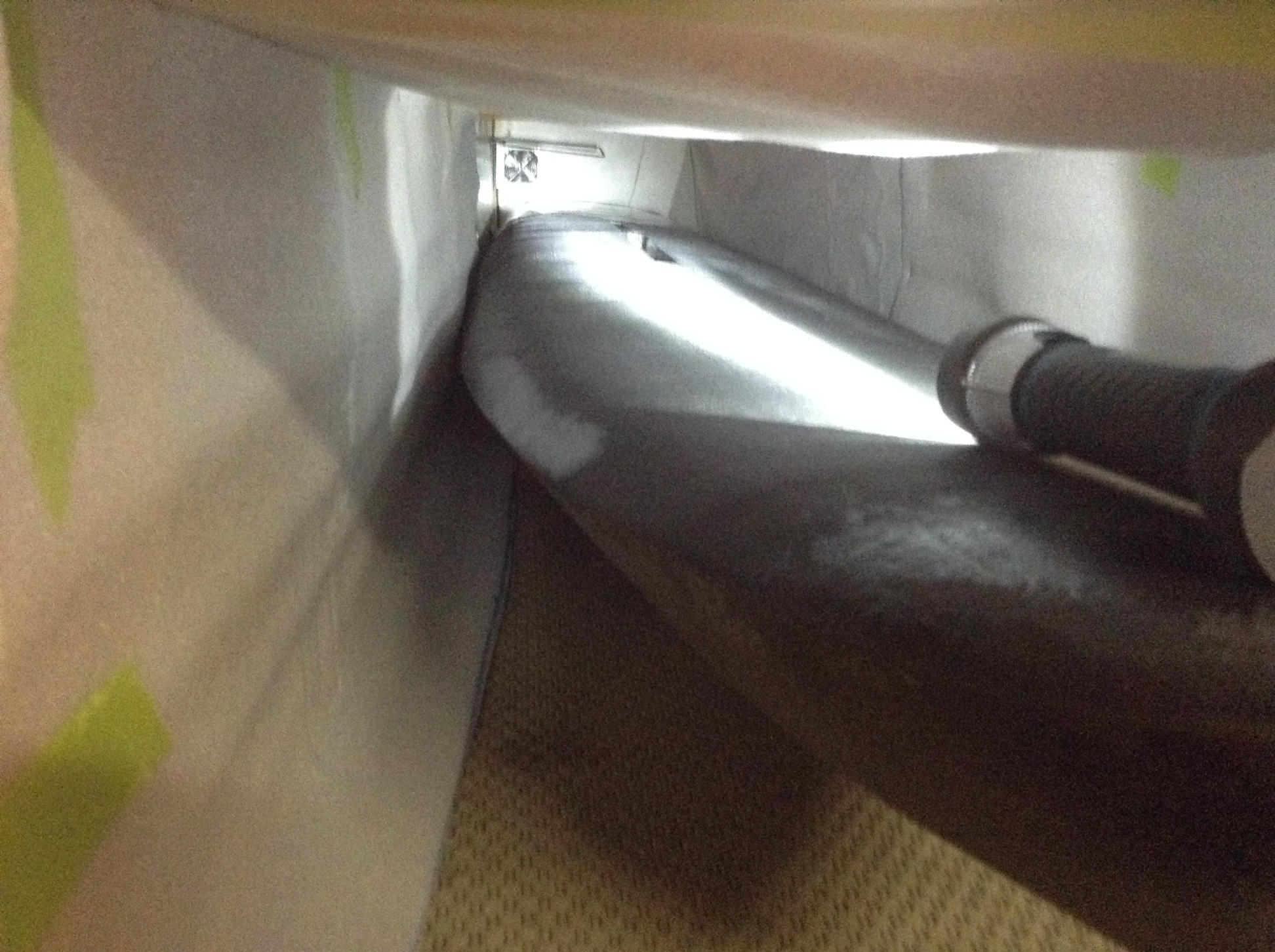
To allow the mould to be used in a vacuum bag it must be near air tight. When inside the vacuum bag the air pressure inside the mould must still remain at atmospheric pressure and not be draw down to a vacuum (which would deform or crush the mould). A perfectly air tight mould would be ideal but in reality there may be small leaks through the surface of the mould. To compensate for possibility of leaks in the mould surface, a \(5\,\)mm vent hole was drilled in the back of the mould. The mould was then placed in the vacuum bag and a square is cut in the bag around the location of the vent hole. The edge of the square cut out was then sealed against the mould surface with masking tape, Figure 25.
A dry run leak test was then performed with the mould in the vacuum bag and the system was found to hold a good vacuum with very little leakage. If the vent hole is making a whistling sound or you can feel a suction pressure on it means the mould is not very air tight. Leaks in the bag can also be detected by listening for them. The point is you do not need a perfectly air tight system, just sufficiently air tight to be able to hold the desired vacuum, with ideally a limited need to continually run the vacuum pump. Further details of the vacuum pump control are given in section Vacuum pump and controller.
Several coats of mould release wax were applied to the mould. I did not want to take any chances with the lamination releasing from the mould. So I also placed peel ply directly against the mould prior to laying up the carbon.
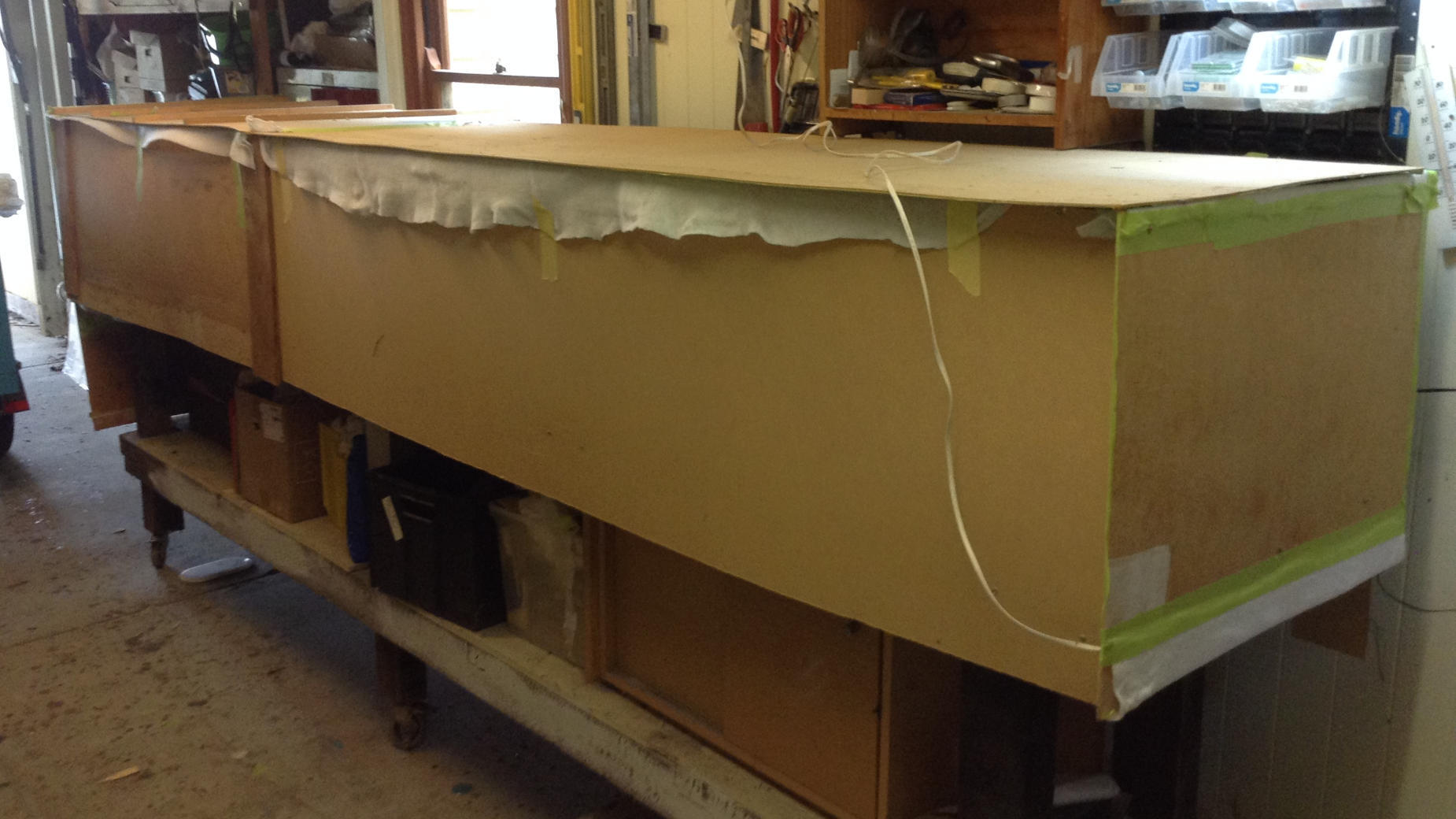
Pre-bending the HDF
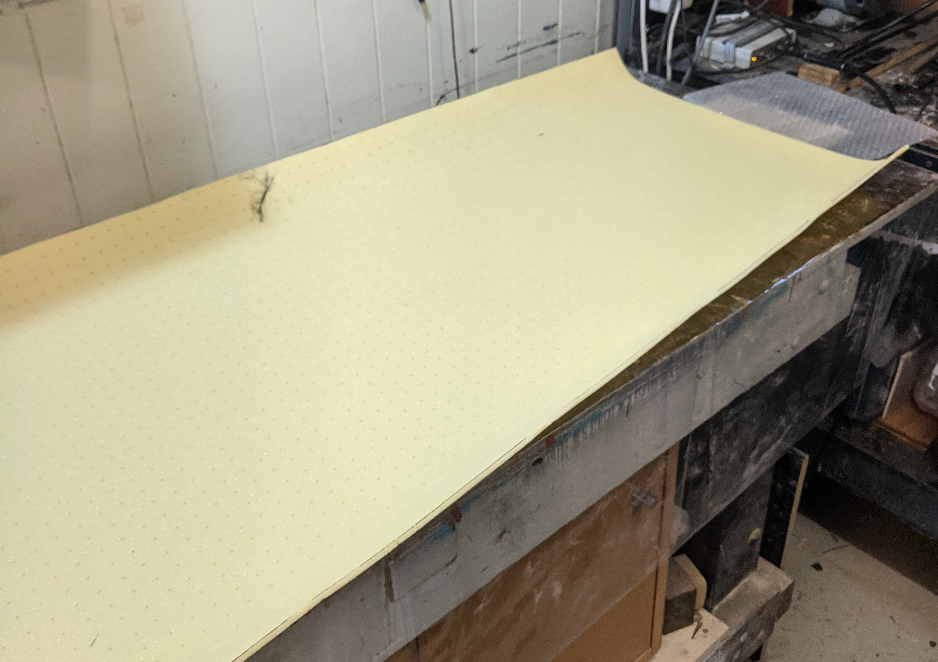
The HDF was pre-bent by strapping it onto the mould and also placing it under a vacuum for a few hours. Simultaneously, heat was applied to the foam with a heat-gun. Particular attention needed to be paid to the tightly curved regions around the bow. There was significant “spring-back” once the foam is removed from the mould and the idea was to just to get the foam to be closer to the mould contour. Figure 26 shows a deck piece of HDF after pre-bending it.
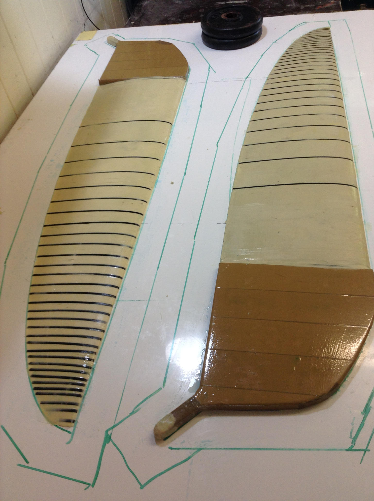
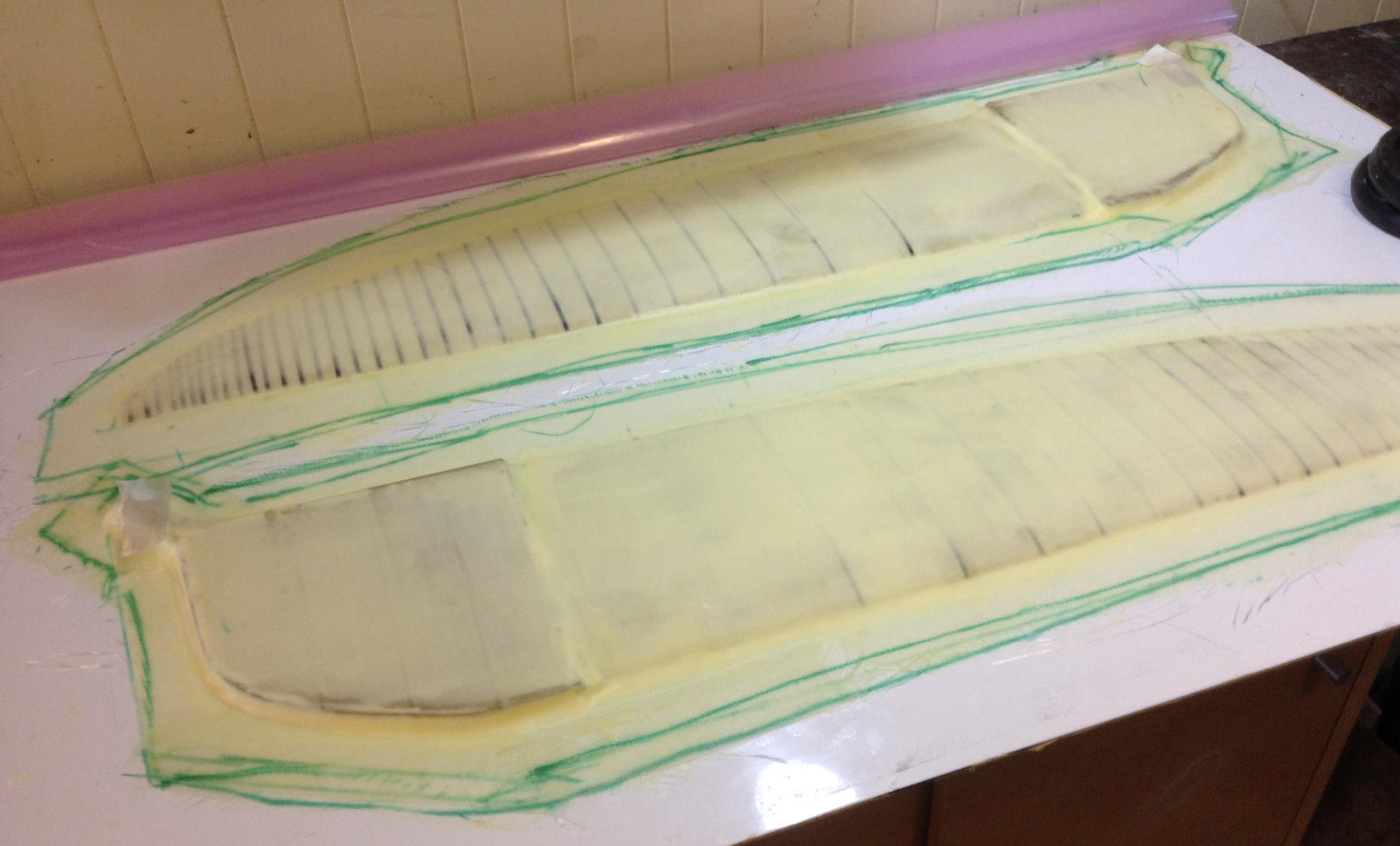
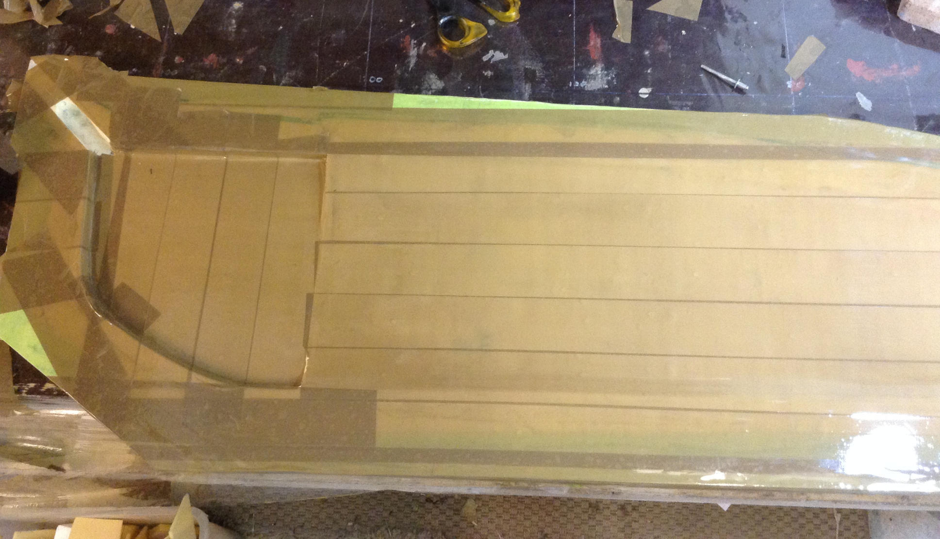
Vacuum bagging of inner carbon laminate and HDF
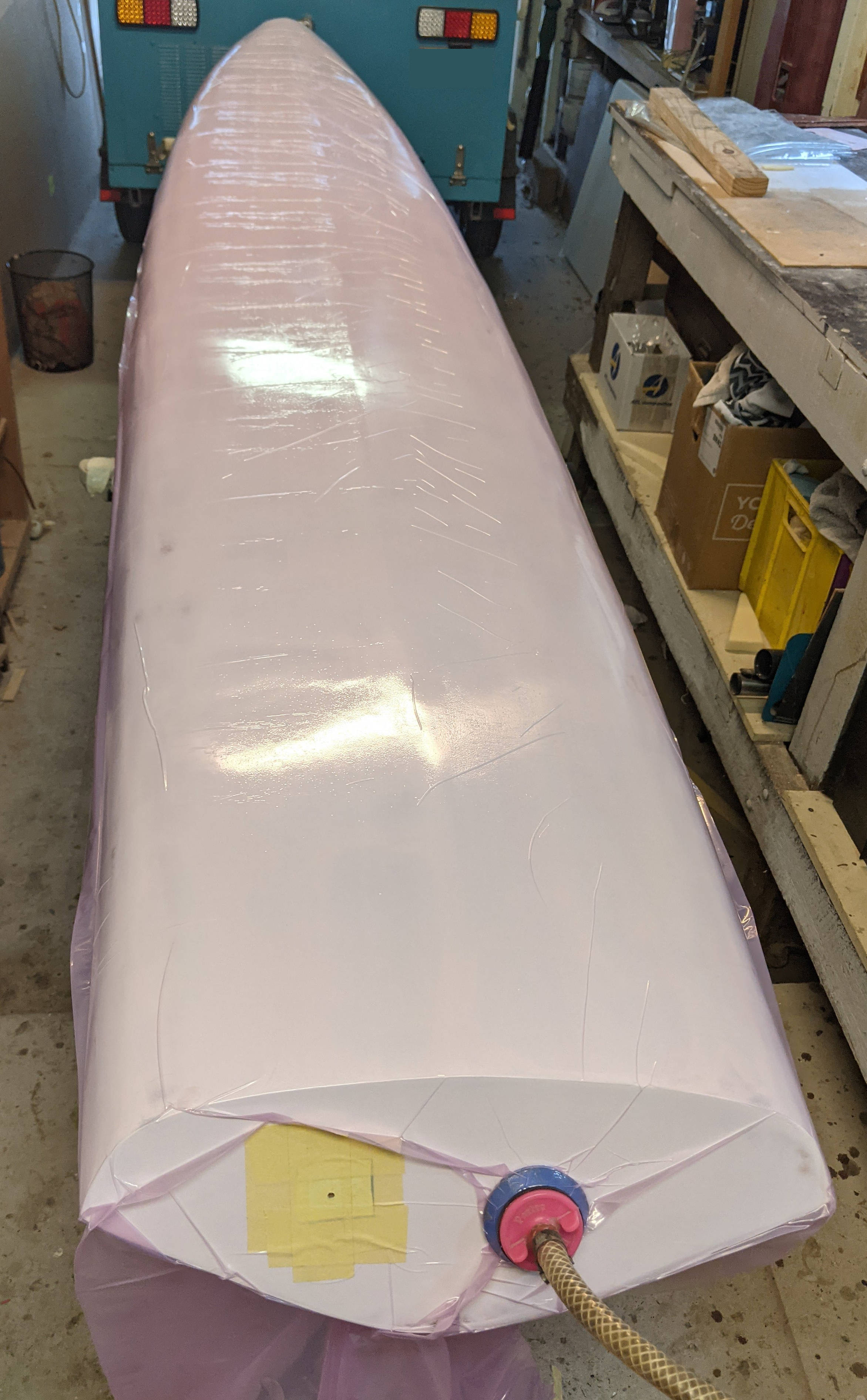
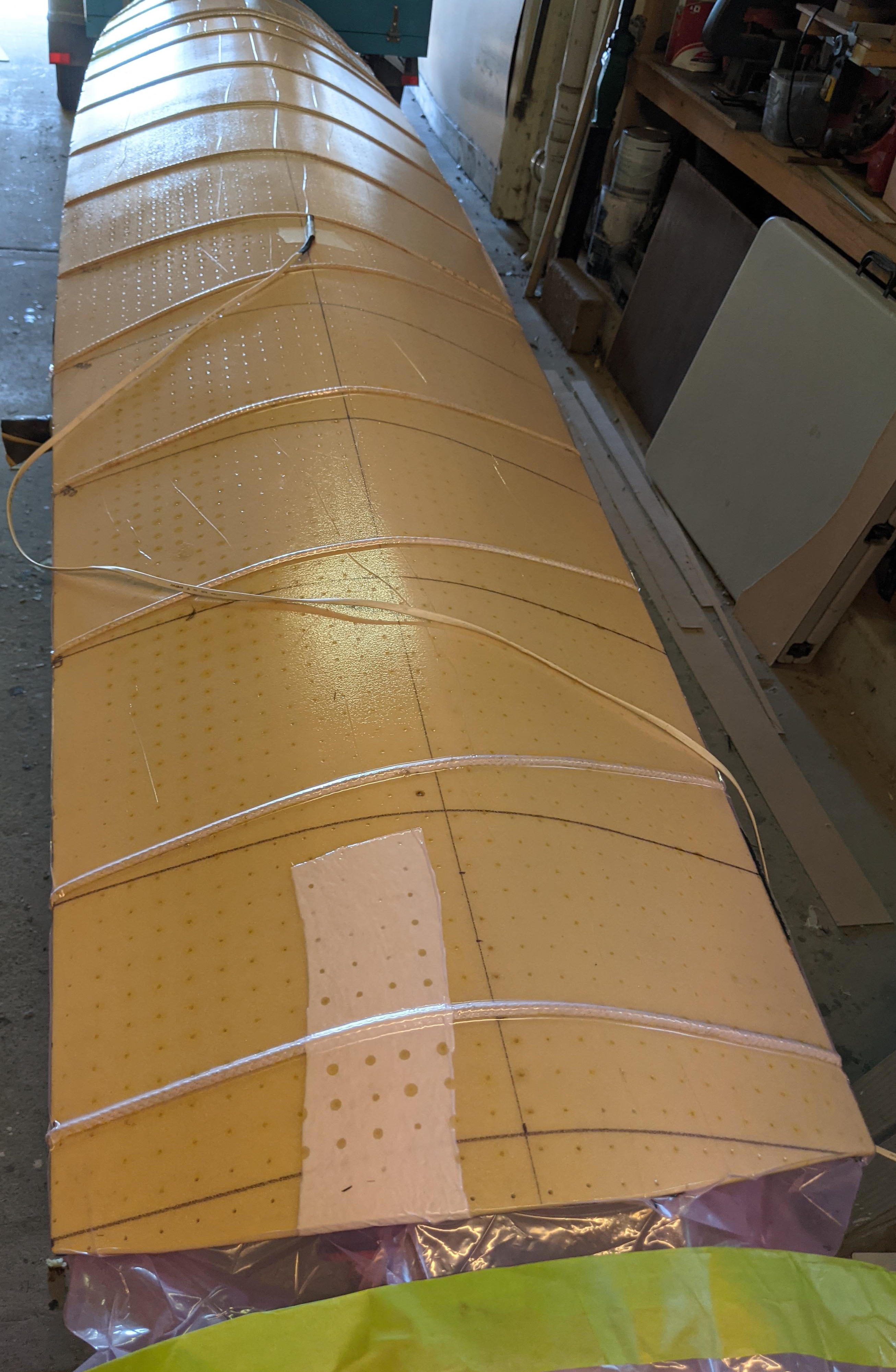
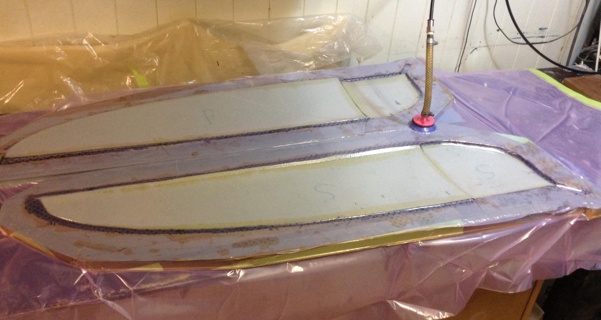
A layer of peel ply was first placed directly against the mould, Figure 27. The deck was laid up first and comprised a single layer of \(200\,\)g/m\(^2\) plain weave carbon, followed by \(5\,\)mm thick HDF. At this stage I did not layup the outer layer of carbon. This would be done later, once I had joined the deck to the hull. A long rope was wrapped around the HDF and mould and pulled tight to hold everything in place prior to placing it in the vacuum bag. Figure 28 shows the deck lamination inside the vacuum bag and under vacuum of around \(40\,\)kPa absolute pressure (i.e. \(60\,\)kPa below atmosphere). I used a slow set epoxy so kept the vacuum applied for 12 hours. The de-moulded deck is shown in Figure 29 with peel ply still attached.
Prior to doing the hull layup, a 25mm wide strip of HDF/glass 5mm thick sandwich was laid up along the chine, as shown in Figure 30. The purpose of this strip is to extend the width of the hull mould surface by \(5\,\)mm. This allowed the deck and hull to be glued together using a lap joint as shown in Figure 31. The edge of this strip was filled and faired into the hull surface.
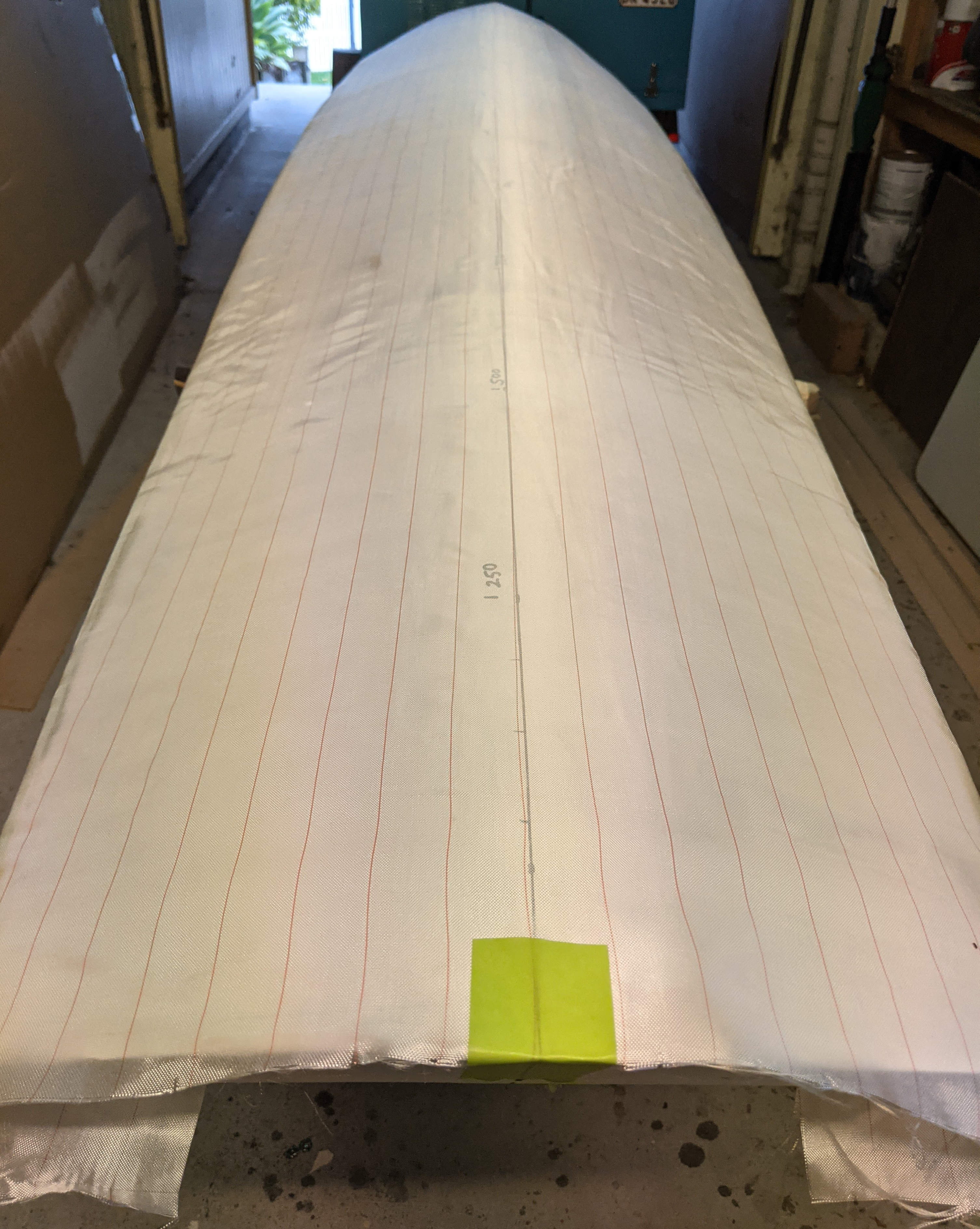
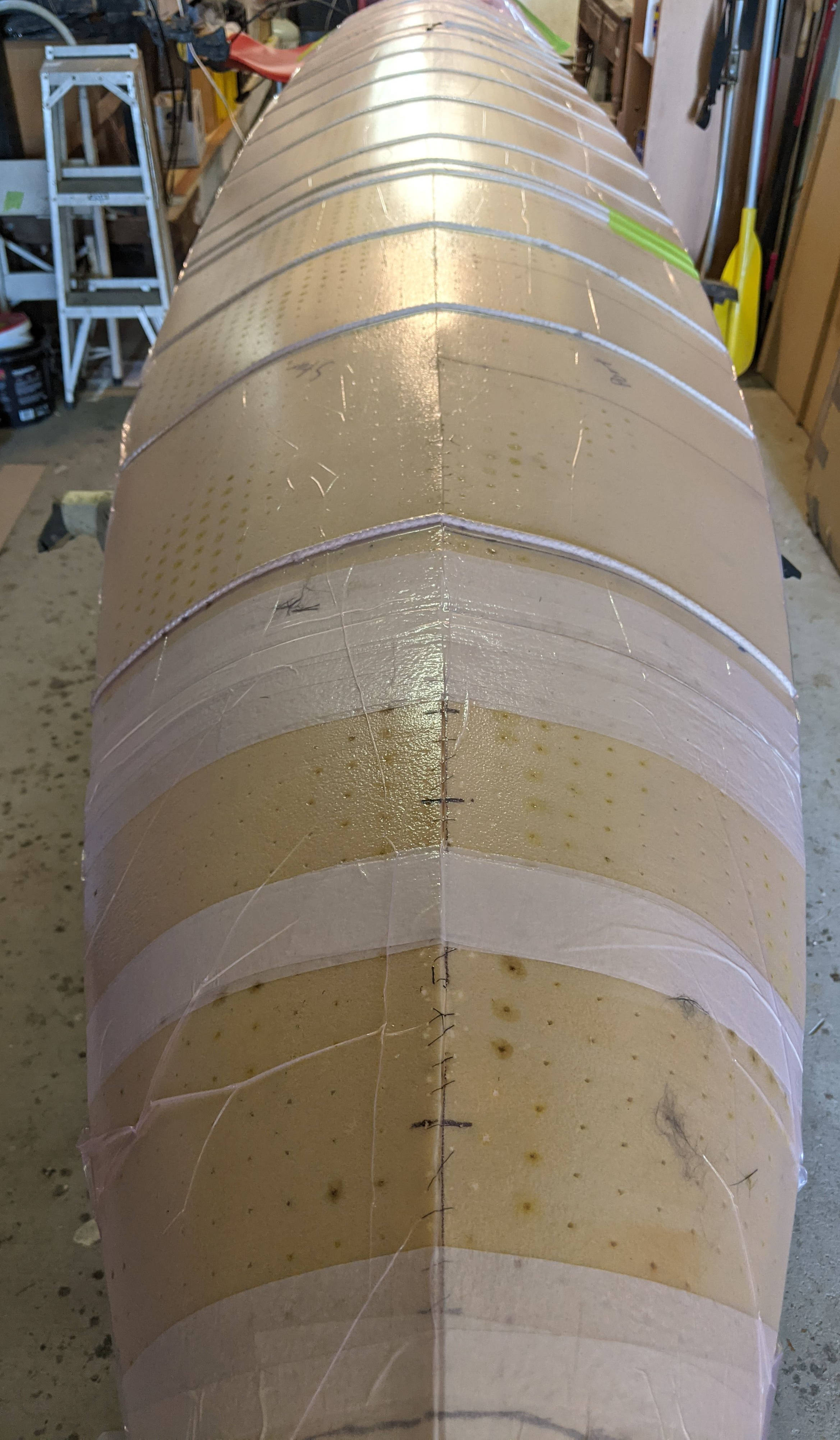
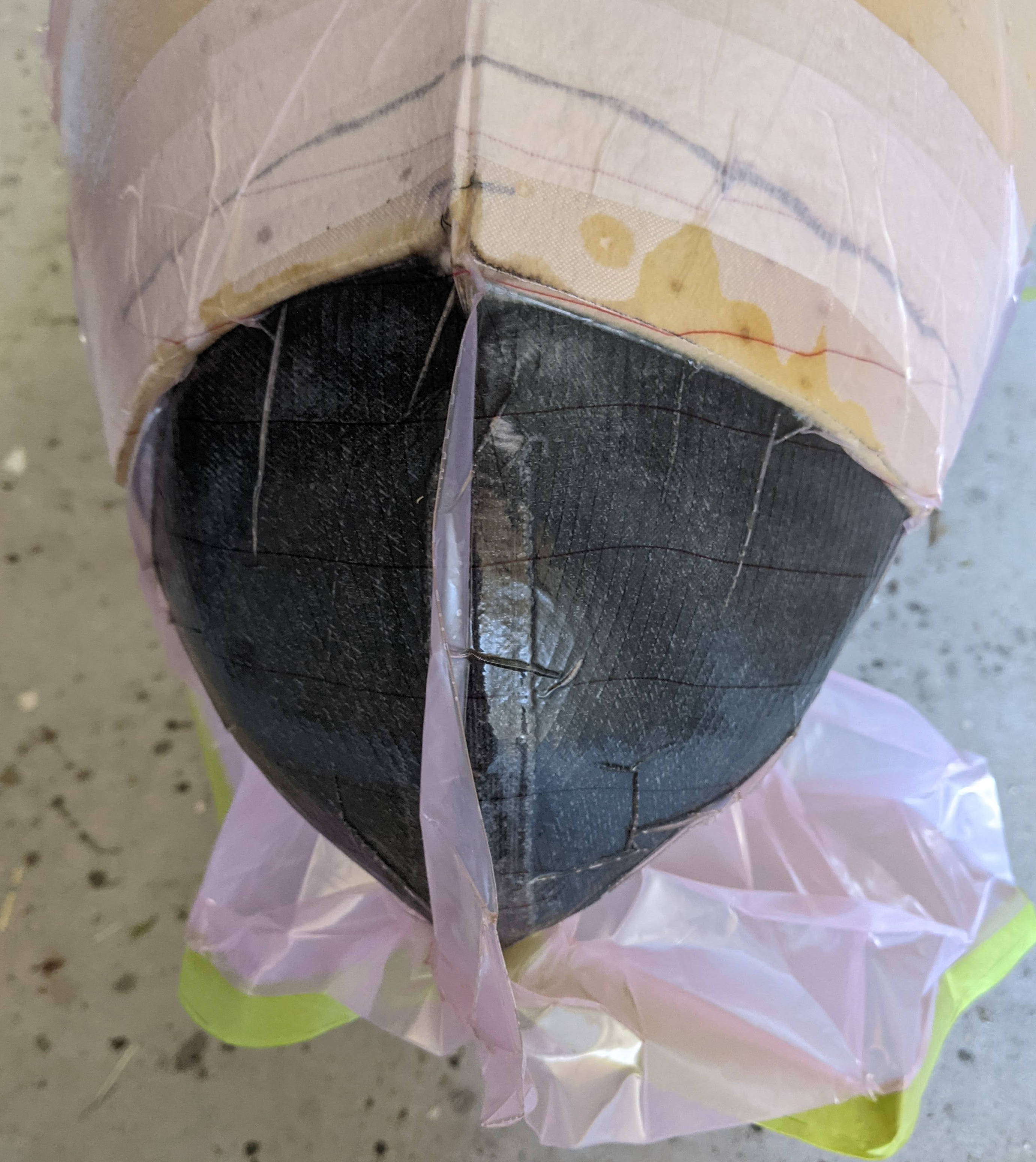
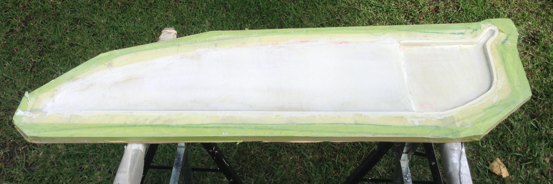
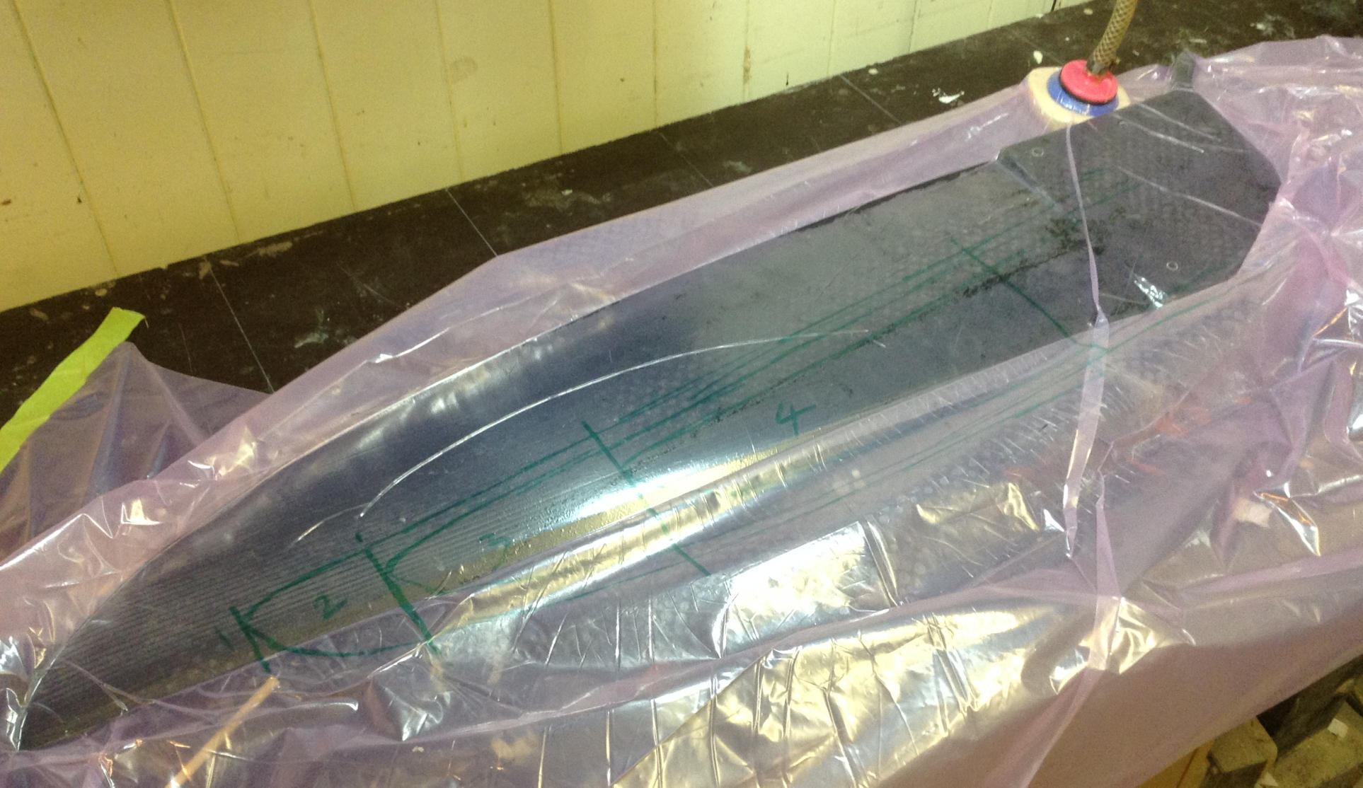
The hull was then laid up and comprised a single layer of \(155\,\)g/m\(^2\) biaxial weave carbon (Figure 32), followed by \(5\,\)mm thick HDF. A rope was then wrapped around the HDF/mould and tensioned to keep everything in place. The mould was then placed in the vacuum bag for 12 hours, Figure 33. The HDF around the bow was made up of several pieces which were thermoformed into the required shape. I deliberately left these pieces out during the initial vacuum bagging run, as I did not want get distracted with getting these pieces correctly aligned and positioned. I then did a second vacuum bagging run where I focused on the bow section. The demoulded hull is shown in Figure 34.
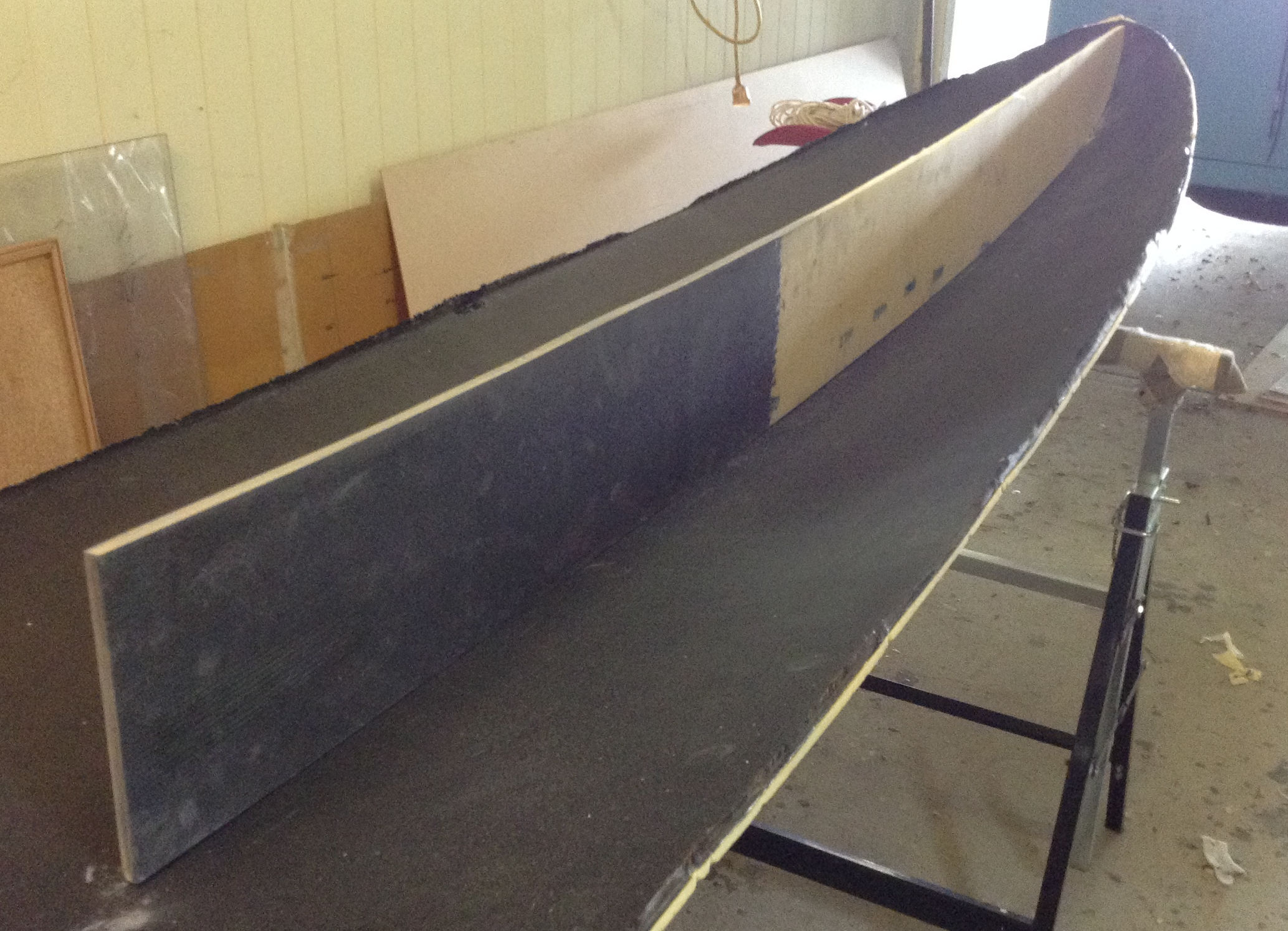
During this stage the outer lamination was not applied onto the skins. Hence, when removed from the mould there is a degree of “spring-back”. However, the skins still have sufficient compliance and when glued to the internal frame their desired profile was restored.


Internal frame
An internal frame was constructed from \(10\,\)mm HDF laminated with either fibreglass or carbon. For heavy loaded locations, such as the fin box and centre-board box, \(155\,\)g/m\(^2\) carbon was used, otherwise \(86\,\)g/m\(^2\) fibreglass was used. The purpose of the internal frame is twofold. Firstly it is structural, providing support to the skins and the high load areas such as mast track, centre-box and fin-box. Secondly it is form-work, providing the “true” profiles to which the skins are pulled onto and glued to.
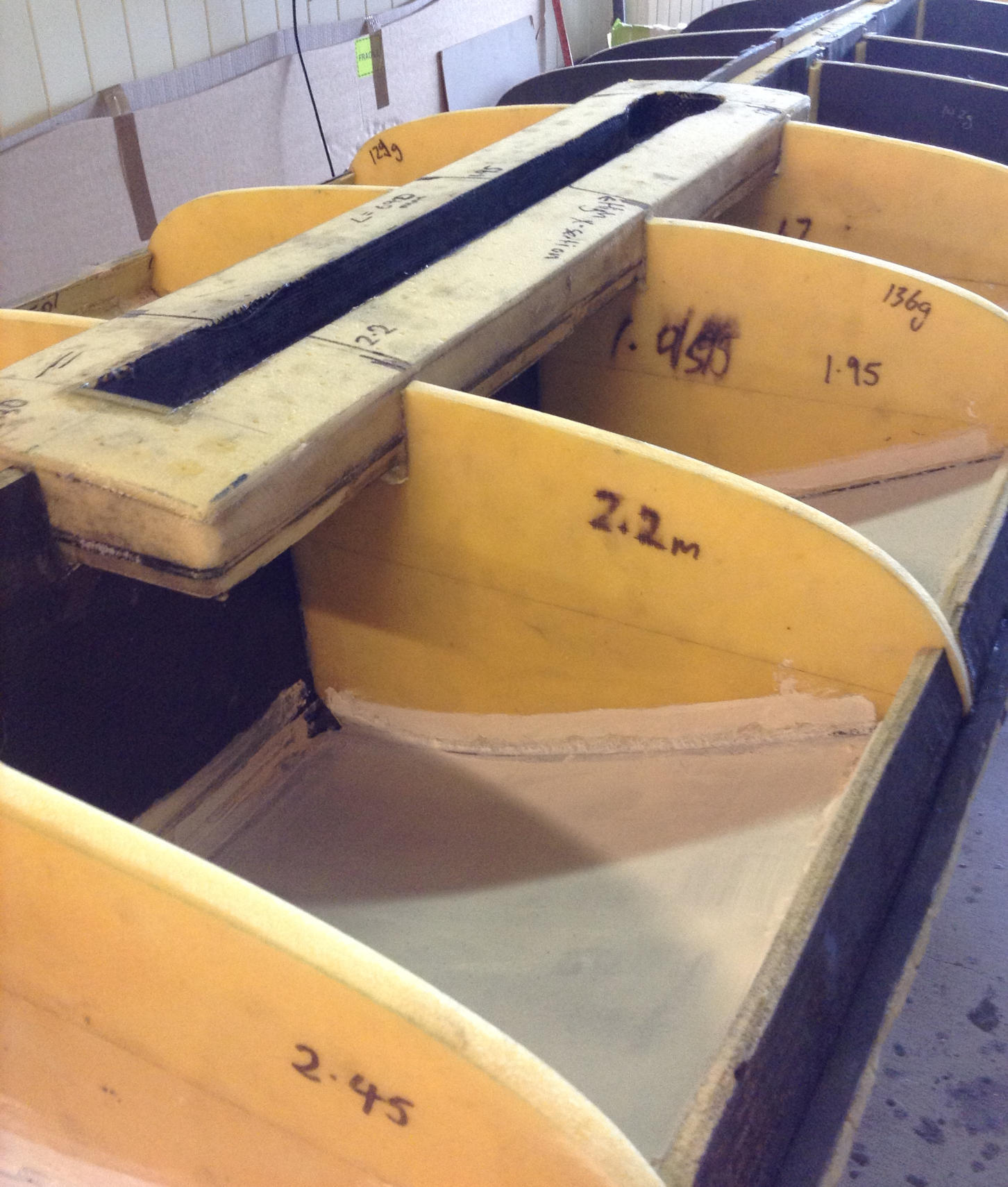
Bulkheads
The bulkhead locations are tabulated in Table 4 and these locations are marked on the board planform in Figure 35. Using “Freeship” software the coordinates of the bulkheads were exported at these stations and these coordinates are attached in the Excel file below. The coordinates were then offset by the the board skin thickness, which was estimated to be \(5.5\,\)mm when accounting for the thickness of the carbon laminate. Using a vector drawing script called asymptote the coordinates were transformed to smooth templates and printed A0 size paper and the pdf is attached below.
FreeShip coordinates at bulkhead locations X-Stations.xlsx
Bulkhead template profiles Xstations_A0.pdf
| Index | x (mm) | lamination |
| Stern | 0 | carbon |
| 0 | 245 | carbon |
| 1 | 350 | carbon |
| 2 | 625 | glass |
| 3 | 835 | glass |
| 4 | 1050 | carbon |
| 5 | 1300 | carbon |
| 6 | 1450 | carbon |
| 7 | 1700 | glass |
| 8 | 1950 | glass |
| 9 | 2200 | glass |
| 10 | 2450 | glass |
| 11 | 2700 | glass |
| 12 | 2950 | glass |
| 13 | 3200 | glass |
| 14 | 3450 | glass |
| 15 | 3700 | glass |

Stringer
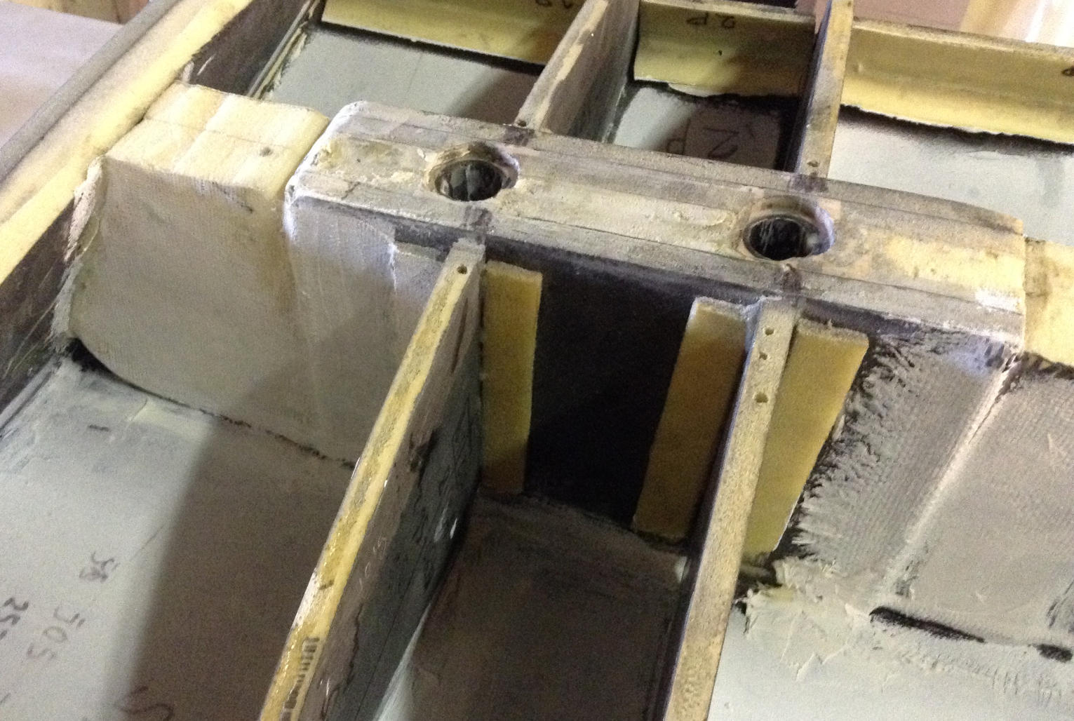
The internal frame incorporated a stringer. Forward of the centre-box (\(x>1600\,\)mm) the stringer is \(10\,\)mm HDF laminated with fibre-glass and carbon as shown in Figure 36.
Centre-board box
The centre-board box was made from \(5\,\)mm HDF laminated with carbon. The pivot point for the centre-board was made from many layers of carbon and these parts were set into the \(5\,\)mm HDF prior to laminating, Figure 37. The area where the centre-board loads the box had an additional sandwich of \(10\,\)mm HDF (i.e. total sandwich thickness of \(15\,\)mm). Further, the inner panel of the centre-board box was reinforced with multiple layers of carbon fibre. The panels were laid up against a flat laminating table and placed under vacuum.
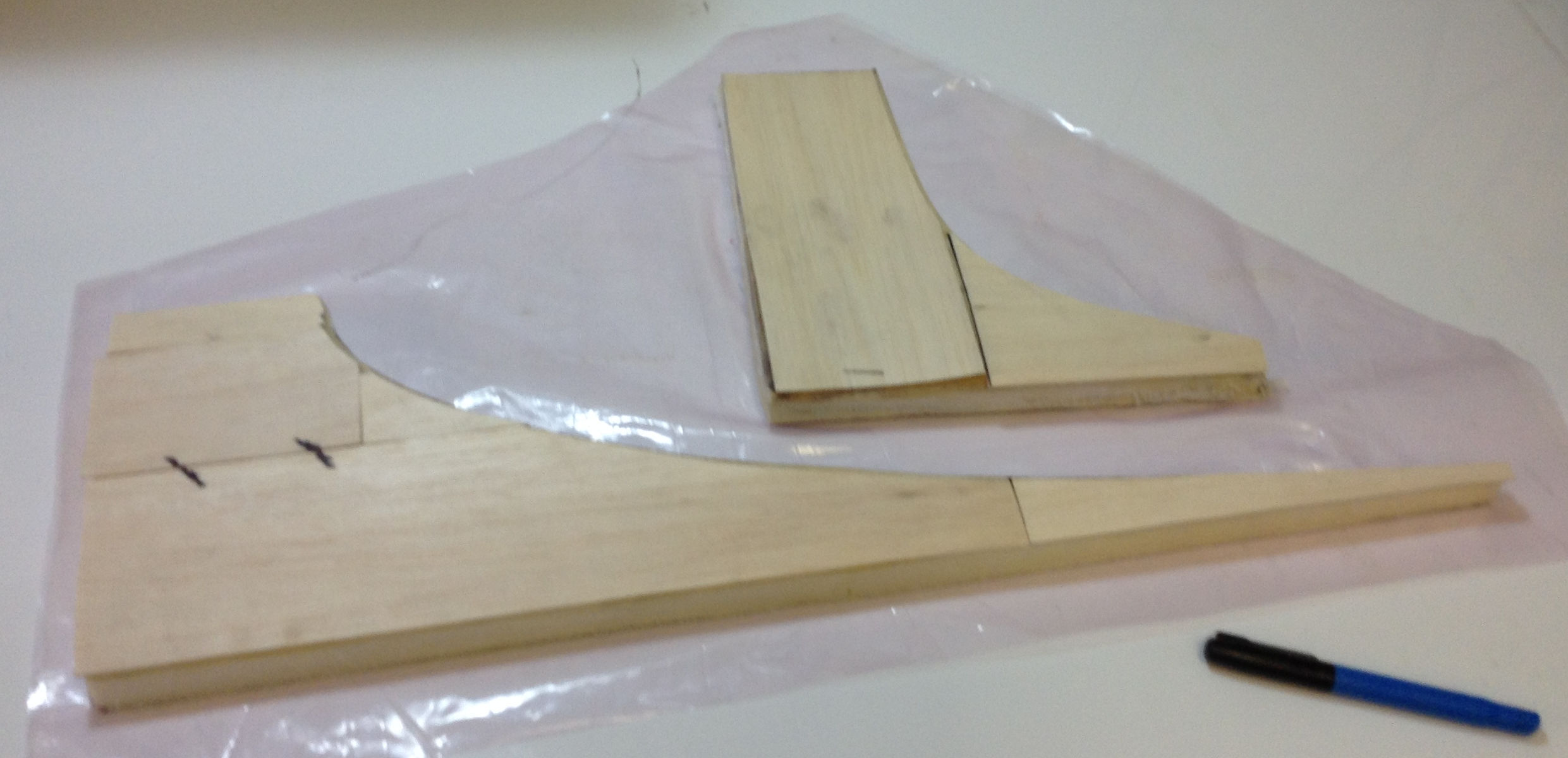
Polyurethane (PU) foam of thickness \(25\,\)mm was used to separate the two panels. This foam was shaped to match the centre-board planform Figure 38. The thickness of the centre-board head was approximately \(25\,\)mm. Hence, an additional shim of \(1\,\)mm thick balsa was glued to one face of the PU foam to create a slot width of \(26\,\)mm. The panels were then glued to the PU foam and the completed centre-board box is shown in Figure 39.


Fin-box
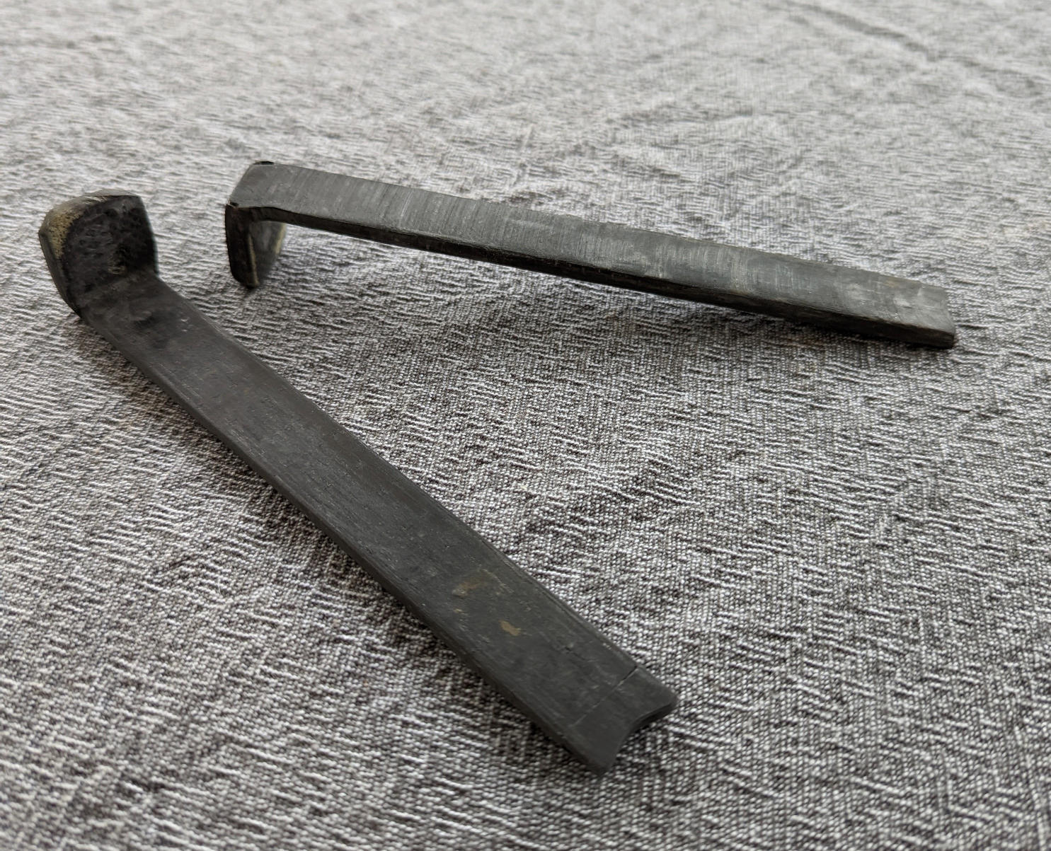
A Chinook standard size Tuttle fin-box was used. The Chinook is a plastic fin-box which was strengthened by encasing in a carbon-fibre sandwich. The thickness of the board is significantly greater than the height of the fin-box. Therefore, extension tubes were added to the top of the fin-box to allow the fin bolts to be recessed by approximately \(55\,\)mm from the deck of the board. These extension tubes were made from an broken boom tail piece and are shown in Figure 40.
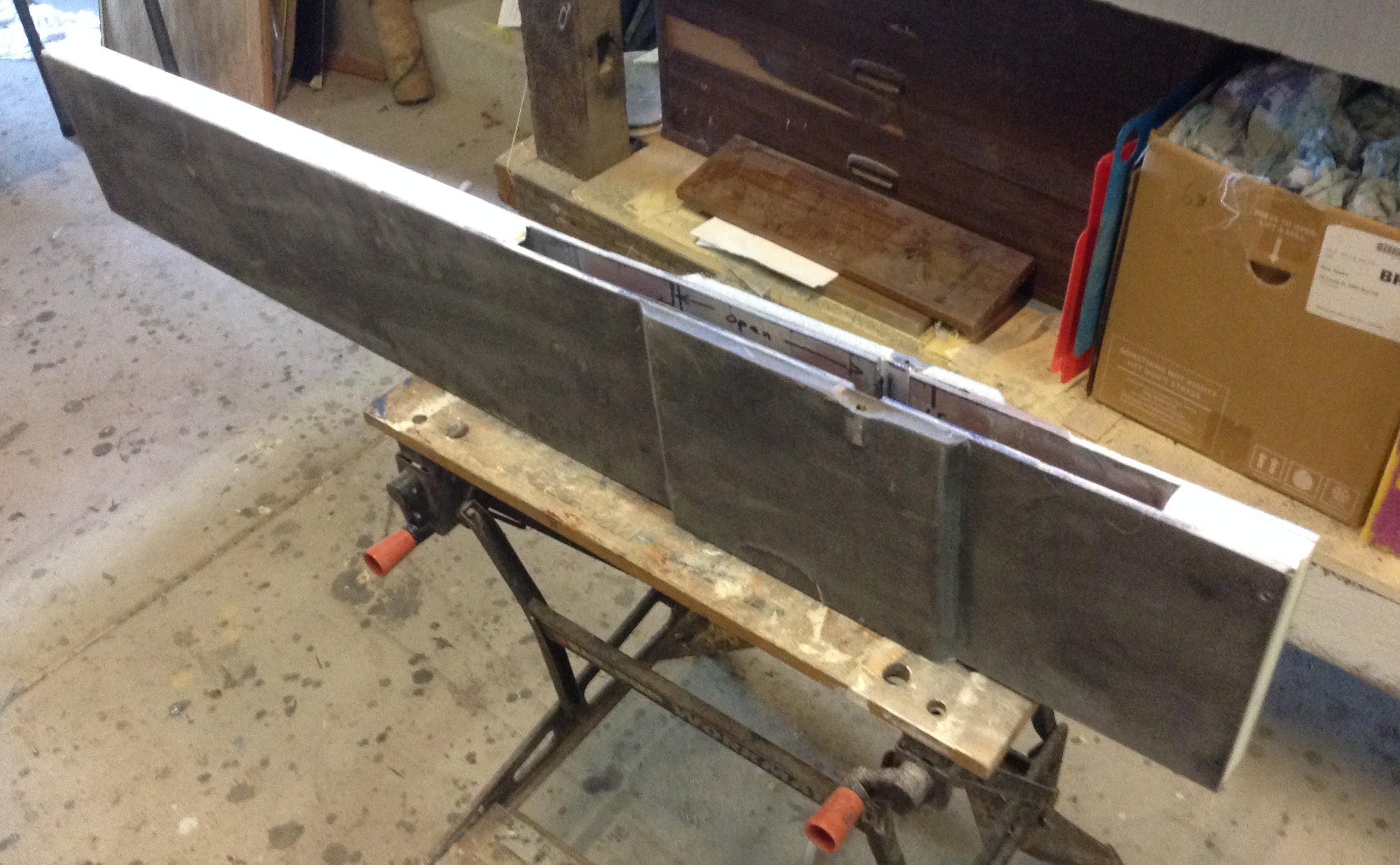
Using a combination of PU foam and HDF, a block of foam was shaped to fit around the plastic fin-box, as shown in Figure 41. Carbon-fibre sandwich panels (thickness of \(10\,\)mm) were laid up on a laminating table and placed under vacuum. The panels were then glued to the fin-box and foam. The finished encased fin-box is shown in Figure 42.


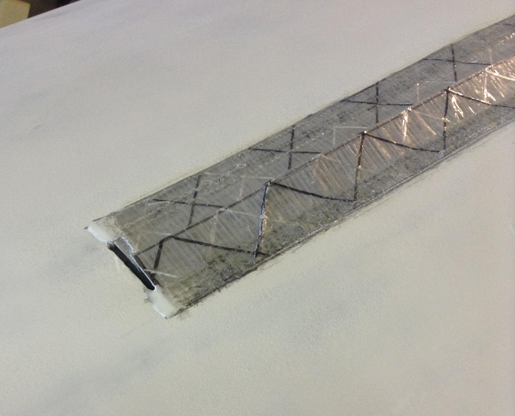
Chine bracket
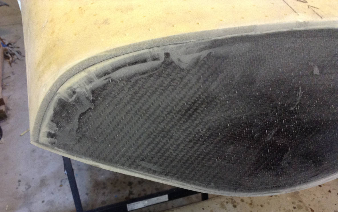
The chine of the board is where the hull meets the deck and there is a distinct change in angle of the cross-section. The Lechner has a chine angle of around \(90^\circ\) which runs the entire length of the board. In windsurfer design this would usually be referred to as a sharp or hard rail.
A chine bracket was constructed to provide structural support at the join between the hull and the deck, Figure 43. The chine bracket was made by adding an equivalent hull strip to the the mould extension piece shown in Figure 30. This then created a bracket with the required chine angle which ran the full length of the board. In the photos shown in Figure 43 the chine bracket has not been installed yet and this will be explained in section Assembly of frame and skins.


Fittings
Mast track
A “Glide” mast track was sourced direct from the factory where they are made in China. The Glide 2990 windsurfer is a board designed by Bruce Kendall, who incidentally won the gold medal in the Lechner class at the 1988 Olympics. He was very helpful with organising the purchase of the mast track.
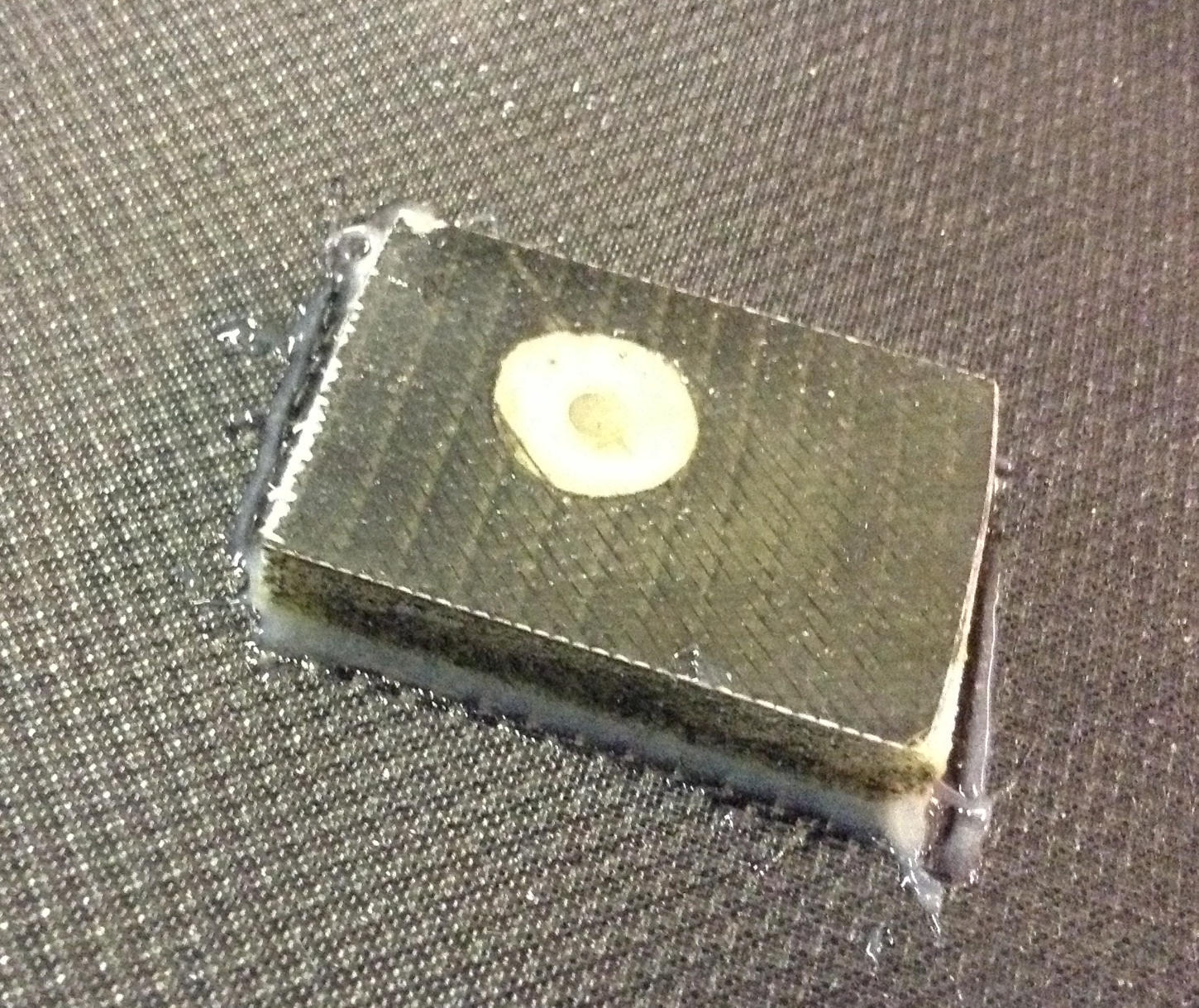
A composite mast-track box was constructed from PU foam, HDF and carbon fibre. The base of the mast-track box was made from \(10\,\)mm thick HDF into which M6 TEE nuts were glued with epoxy, Figure 44. A \(3\,\)mm HDF/carbon sandwich was laminated on top of the \(10\,\)mm base. The cavity for the mast track was made from \(25\,\)mm thick PU foam and \(5\,\)mm thick HDF. This foam was shaped to fit around the mast track, as shown in Figure 45. The internal walls of the cavity laminated with \(5\,\)mm thick HDF/carbon sandwich.
The overall layup of the mast track box is summarised in Figure 46. All the foam layers of the mast track box were laminated together with layers of carbon fibre and placed under vacuum, Figure 46.


Footstrap plugs
The footstrap plugs used the same M6 TEE nuts which were used in the mast-track box, Figure 44. These TEE nuts were glued with epoxy into HDF carbon sandwich blocks of \(10\,\)mm thickness. Further layers of carbon were laminated onto the top of these blocks and a layer of fibreglass was laminated to the bottom of the blocks to seal them, Figure 47.
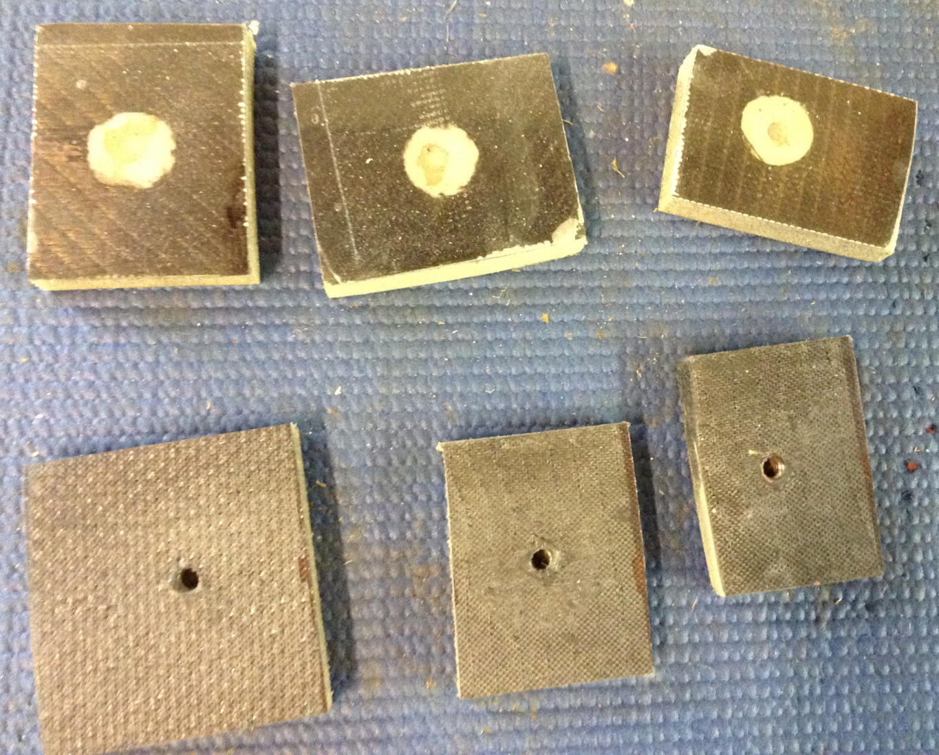
Vent plug
The vent plug is a GORE Air vent. I replaced the the breathable gortex screw with a solid stainless steel (SS) M12 screw. It turned out the SS screw I bought had a 1.75 pitch whereas the GORE vent thread is 1.25 pitch (much harder to find matching screw with 1.25p). In any case the SS screw still tightens up in the GORE vent plug since the plastic thread is compliant enough to accommodate the mismatch. A rubber washer is used to ensure an water-tight seal.
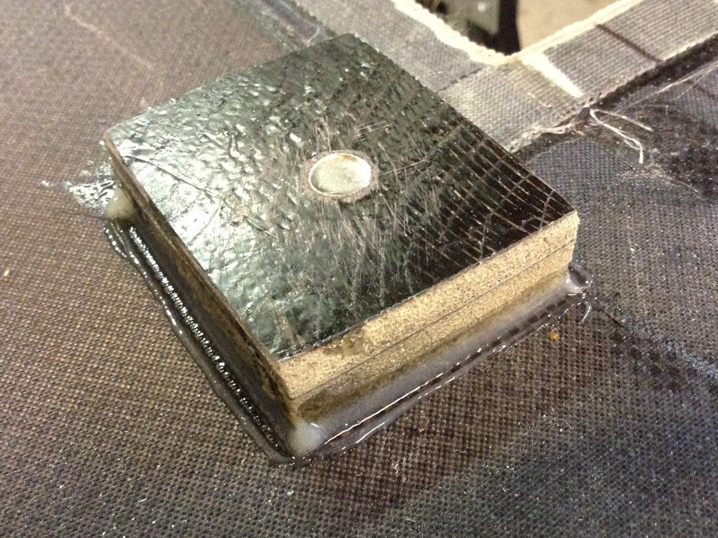
Using two layers of HDF carbon sandwich I created a \(15\,\)mm thick sandwich block, Figure 48. The GORE plug was then glued into this block. Since the total height of the GORE plug was \(20\,\)mm this left \(5\,\)mm of the plug proud of the block, allowing it to pass through the \(5\,\)mm thick deck, Figure 62. The sandwich block housing the GORE plug glued to the underside of the deck is shown in Figure 61.


Assembly of frame and skins
This section outlines the process of assembling the internal frame to the skins. It was important that when assembling the frame it remained true to required form and, as with building the mould, one of the main issues is avoiding any twist along the longitudinal axis.
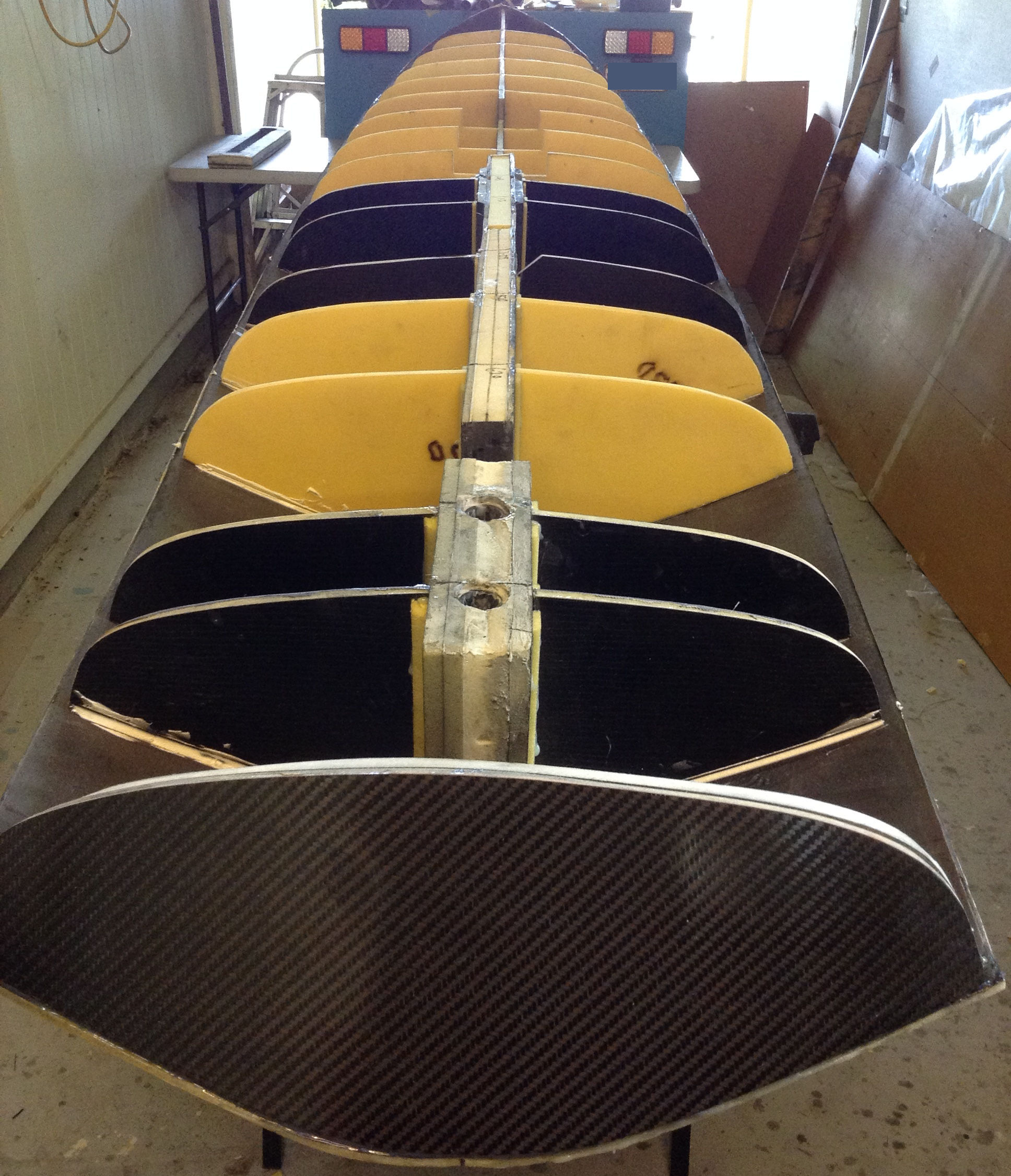
Frame to hull
The first step was to glue the front stringer to the hull using epoxy glue, Figure 49. The hull rocker mated well with the stringer profile. However, to ensure a good bond the parts were held together while the glue dried using temporary screws which passed through the hull skin into the stringer.
The bulkheads which attach to the front stringer were then glued in. I decided not to bother with the bulkhead at \(x=3700\,\)mm. Again temporary screws were used to hold the hull skin to the bulkheads while the glue dried. These screws were particularly important to pull the skin onto the required cross sectional profile. Photos of the front stringer and bulkheads glued into the hull are shown in Figure 50.
Slots were cut in the hull skin to accommodate the centre-box and fin-box. The width of the slots were equal to the external width of the the boxes, so that the boxes could be mounted flush with the hull external surface. Each bulkhead which attached to the boxes was cut into two pieces (i.e. port and starboard sides) and glued to the box. The boxes, along with the attached bulkheads, were then glued onto the hull and the results are shown in Figure 51.
Figure 53 shows the internal frame glued to the hull and in this photo there are gaps in the stringer at the front and back of the fin-box. In these regions PU foam blocks were shaped to fit the stringer profile and then glued in. The PU foam blocks were then laminated with fibreglass, such that the fibreglass also provided a structural load path from the fin-box to the forward and aft structural components, Figure 54.
The chine brackets (see section Chine bracket) were cut into sections to fit between the bulkheads, Figure 55. The brackets were then glued into place and held in place with temporary screws while the glue dried. More photos of the installed chine sections are shown in Figure 56.
The bulkheads and stringer section supporting the mast-track box had appropriate cut-outs to fit around the box, Figure 57. The mast-track box was then joined to the internal frame with epoxy glue. A pair of footstrap plugs were glued to the front of the stringer. These were to allow attachment of a “fairlead” guide line to the bow.
Finally I applied a coat of epoxy barrier undercoat to the carbon-fibre inside the hull, as can be seen in Figure 57.


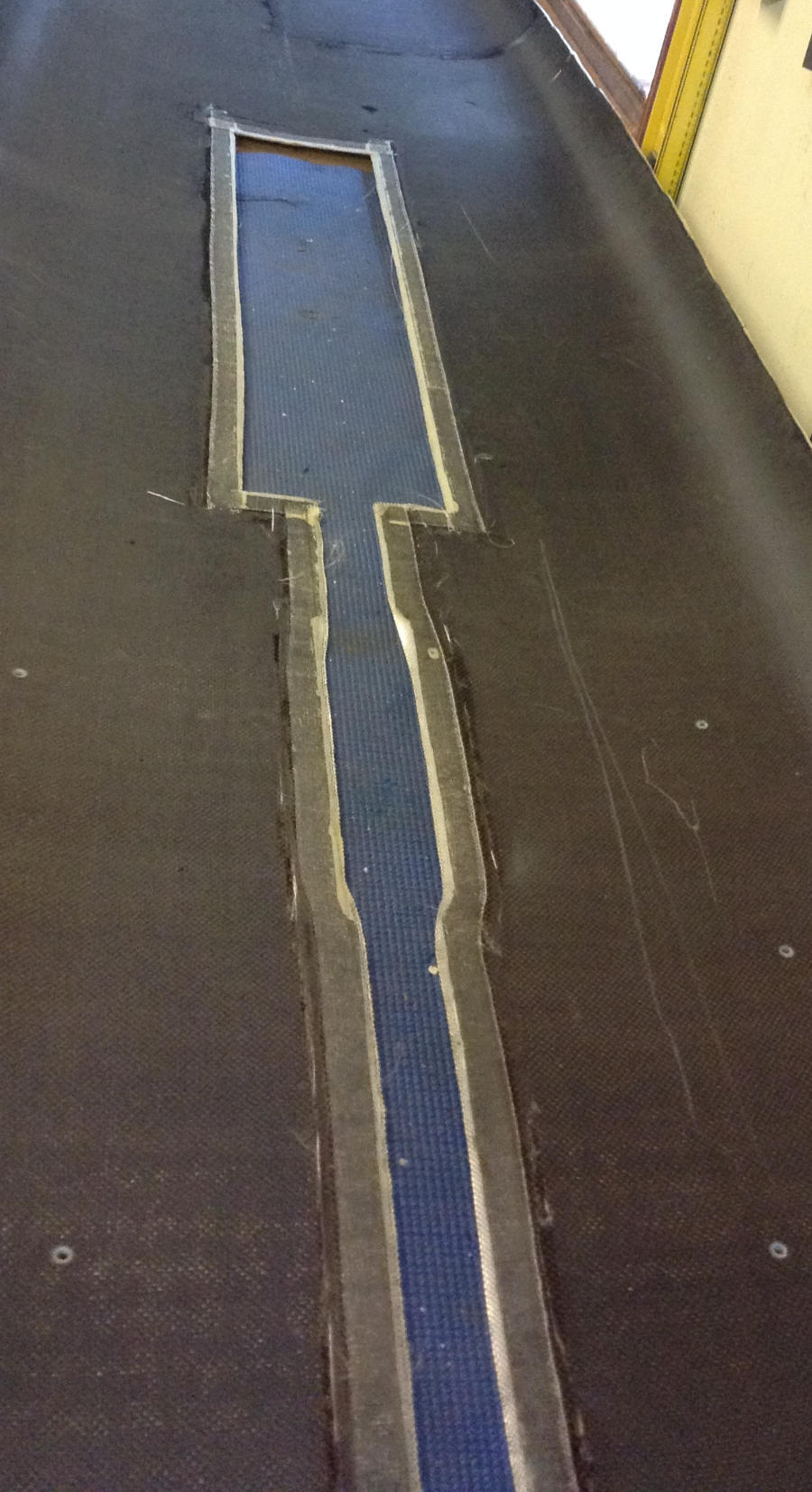
Deck to hull
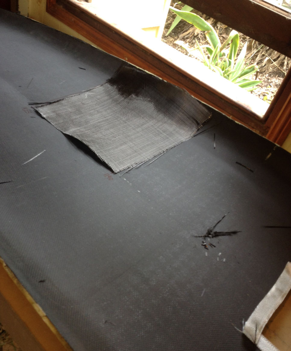
The deck was prepared by cutting the required slots for the mast-track, centre-box and fin-box. All these components pass through the deck and sit flush with the deck external surface. These slots were cut slightly oversized and then a fibre-glass tape was laid around the cut-outs, overlapping the cut-out, Figure 59. This fibre-glass tape provided a more compliant “skirt” around the components and also provided support to glue and filler that would be applied between the component and skin. An extra layer of \(200\,\)g/m\(^2\) carbon was laminated over the area where the deck hatch would be fitted, Figure 59.
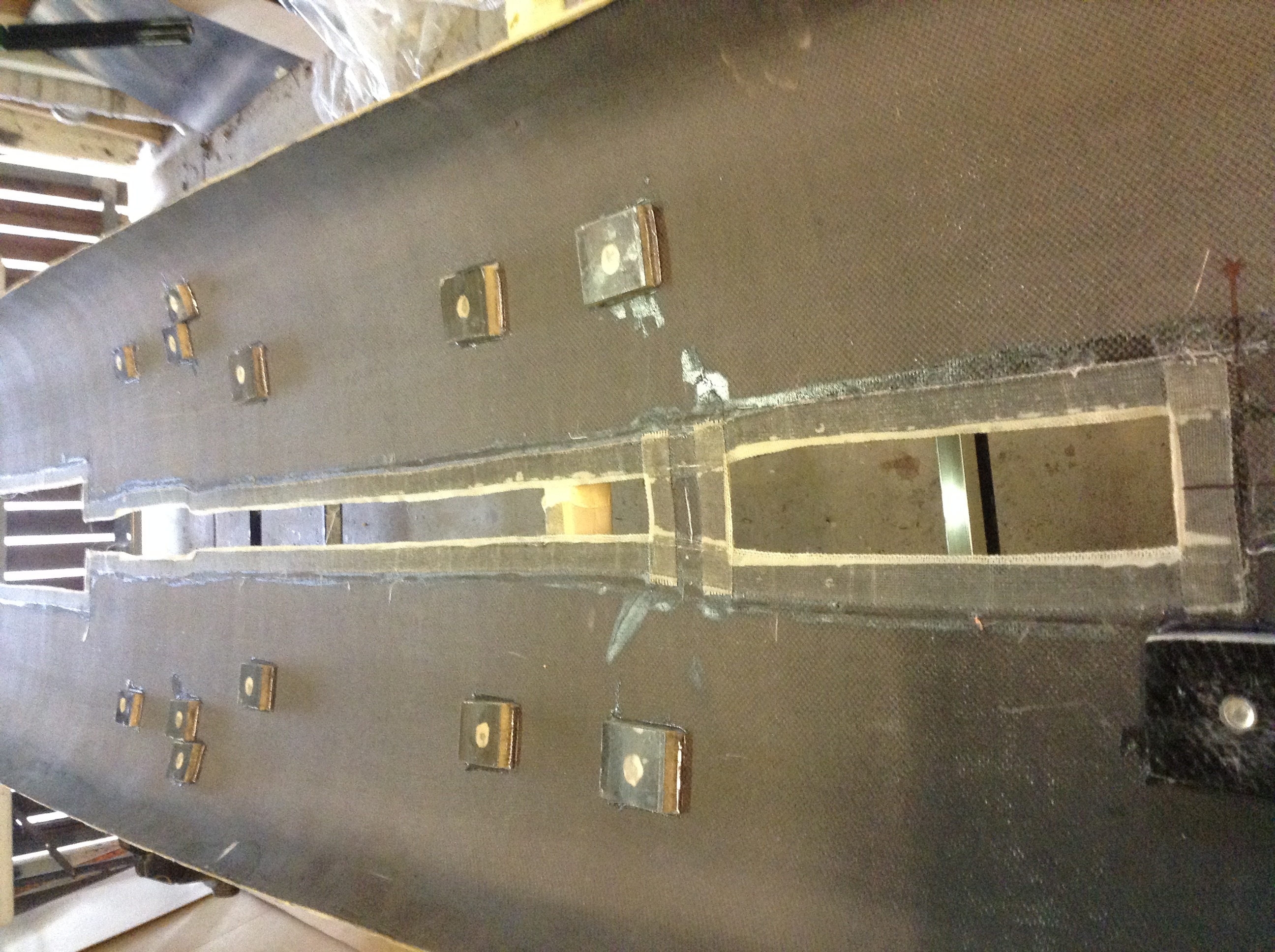
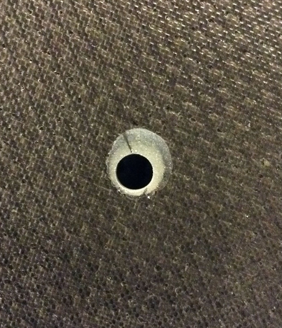
Holes were drilled trough the deck at the location of the footstraps. These holes are first drilled oversized, filled with epoxy glue then drilled at the correct size, Figure 60. This ensures there the hole through the HDF is sealed with epoxy. The footstrap plugs were then glued with epoxy to the inside of the deck, Figure 60.
The deck was now ready for joining to the hull and frame assembly. However, first I gave the hull inside a thorough vacuum to ensure nothing would be left inside the board to rattle around. Epoxy glue was applied along the top of all bulkheads, along the top of the stringer and along the chine brackets. The deck was then positioned in placed and screwed down with temporary screws, Figure 62. Epoxy glue was then worked in between the gaps around the mast-track, centre-box and fin-box.


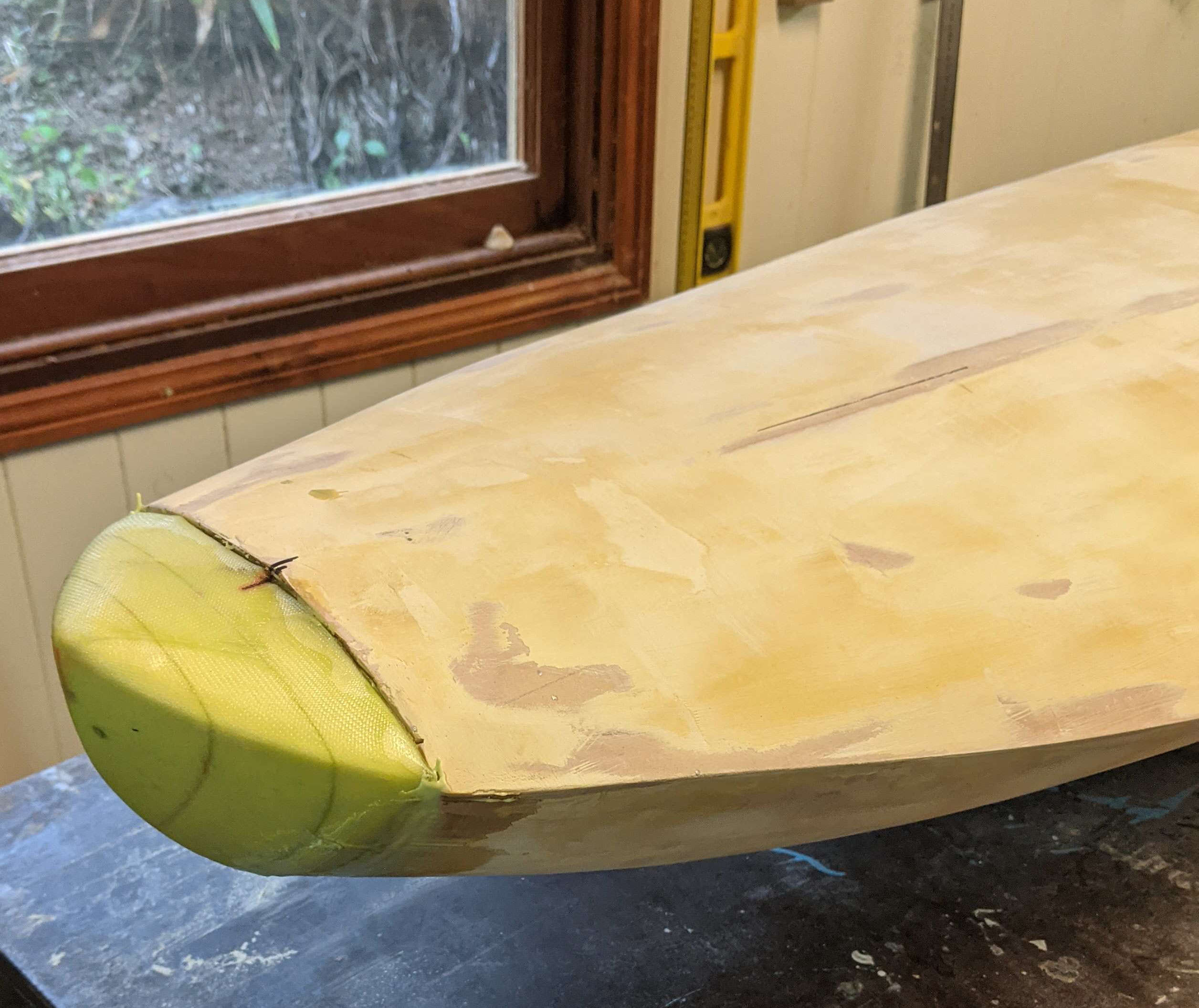
Filling and fairing
All the temporary clamping screws were removed and the holes filled with thickened epoxy filler. The joint between deck and hull had come together well and filler was applied into these small gaps (\(\sim 1\) to \(2\,\)mm), Figure 63. The gap at the bow was larger and filled with pieces of HDF prior to applying the filler, Figure 63. The stern matched up well will the deck and hull and a small amount of filler was required to fill the gaps, Figure 63.
Filling and fairing of the centre-board-box, fin-box and mast-track-box was required and Figure 64 shows these parts faired into the deck.


Vacuum bagging outer carbon laminate
Use of a vacuum bag for the outer lamination is not critical. However, I do find I can achieve a better overall lamination using vacuum. Since the board is hollow it must be close to air tight and vented internally to atmosphere if is going to be placed inside a vacuum bag. This requirement was described for the mould in the section on preparing the mould.
To get the board close to air tight I filled all the HDF perforated holes. While filling these holes was tedious and added more weight I also want to ensure I did not get “print through” of the perforated hole pattern on the laminate. The board was was not as air tight as the mould but I could still achieve a vacuum of around \(40\)% which is heaps enough since I was not trying to bend any HDF. Figure 65 shows the vacuum setup during the lamination of the deck.
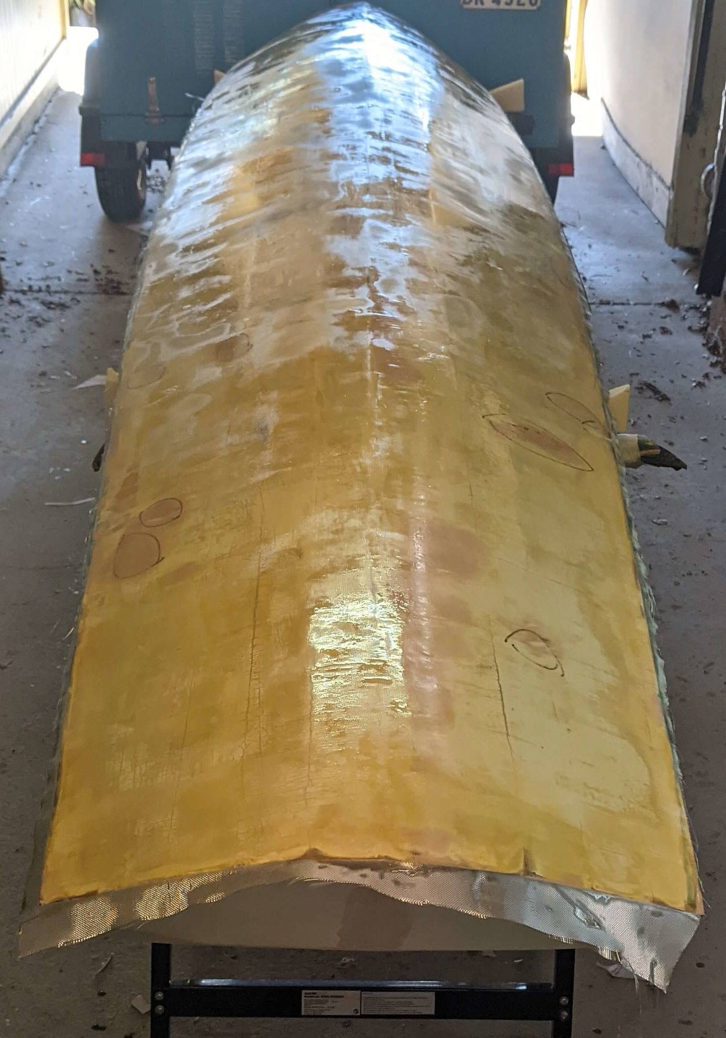
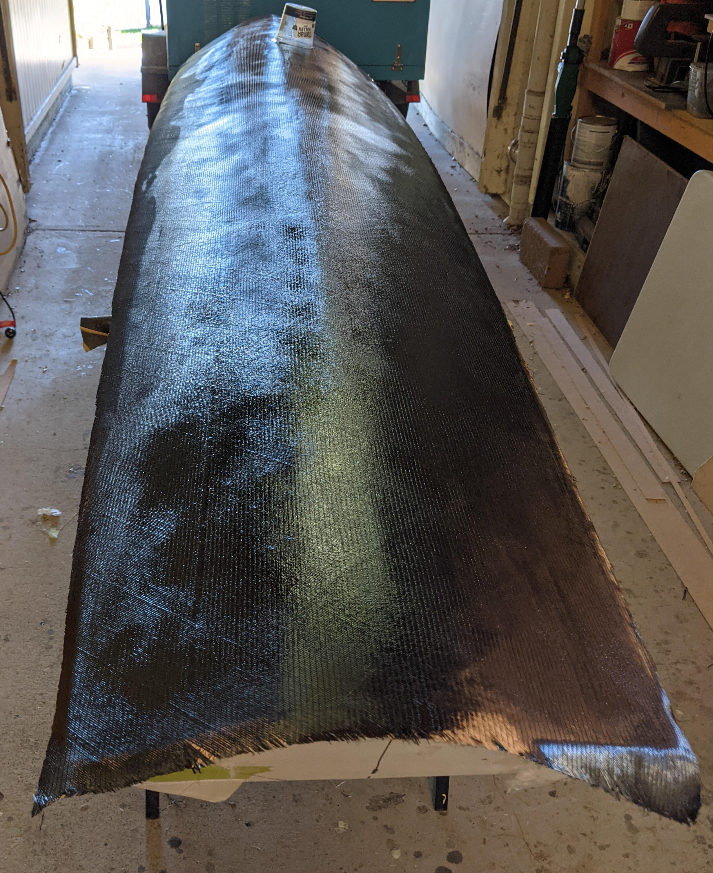
The hull was laminated first using \(155\,\)g/m\(^2\) biaxial weave carbon, Figure 66. This lamination overlapped onto the deck by approximately \(50\,\)mm, also shown in Figure 66.
The deck was laminated with \(200\,\)g/m\(^2\) plain weave carbon with additional patches of \(155\,\)g/m\(^2\) biaxial weave carbon placed around fittings, including over footstrap plugs, Figure 67. The deck lamination did not wrap around onto the hull but did wrap around onto the stern. Figure 68 shows the board after the deck lamination was completed.


Finishing
Fin and centre-board slots
The slots for the fin and centre-board were cut open using a Stanley knife. The edges were sanded flush to the box face using either a file or coarse sandpaper. Views of these slot on the hull are shown in Figure 69.
Post curing
The board was post cured in a hot-box at \(60^\circ\)C for 24 hours. While this is not essential it does increase the strength of the epoxy. The hot-box is described in section Hot-box.
Filling the weave
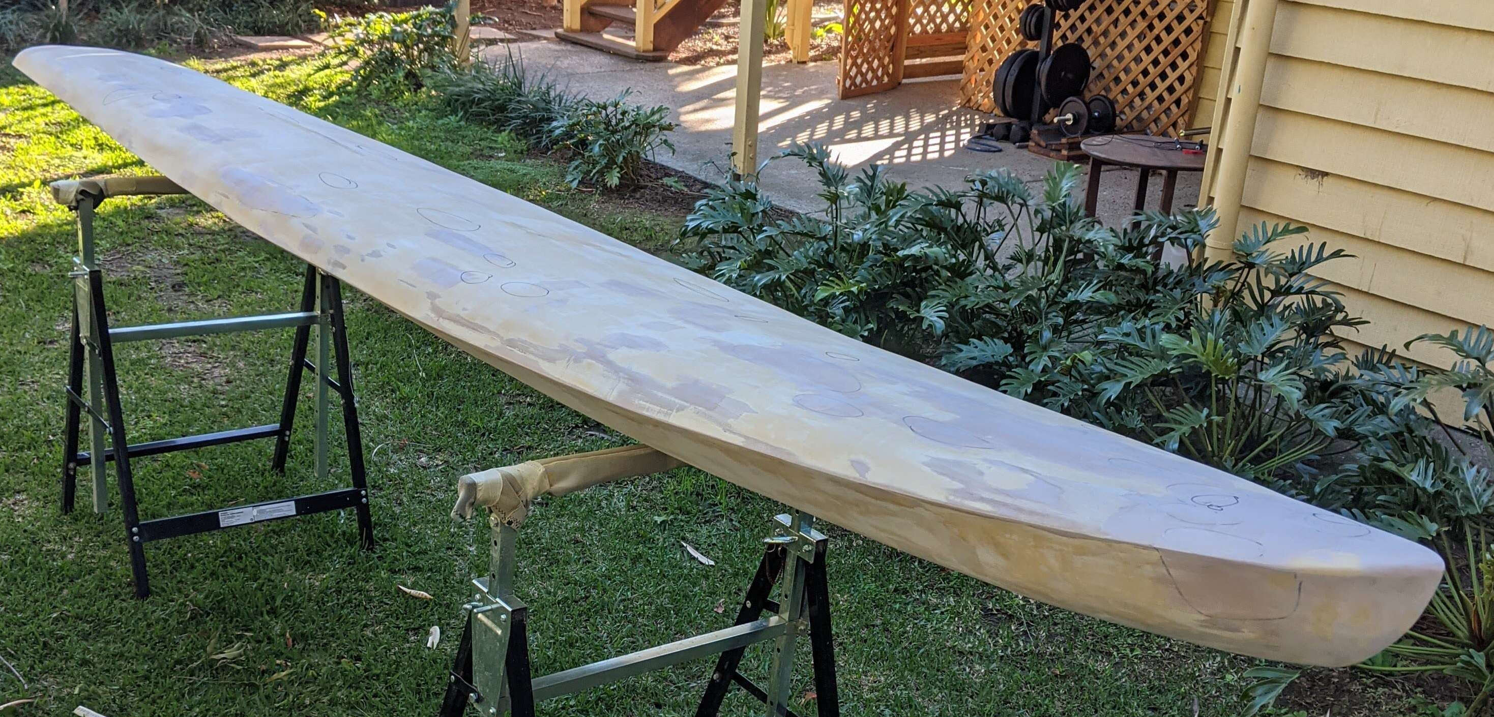
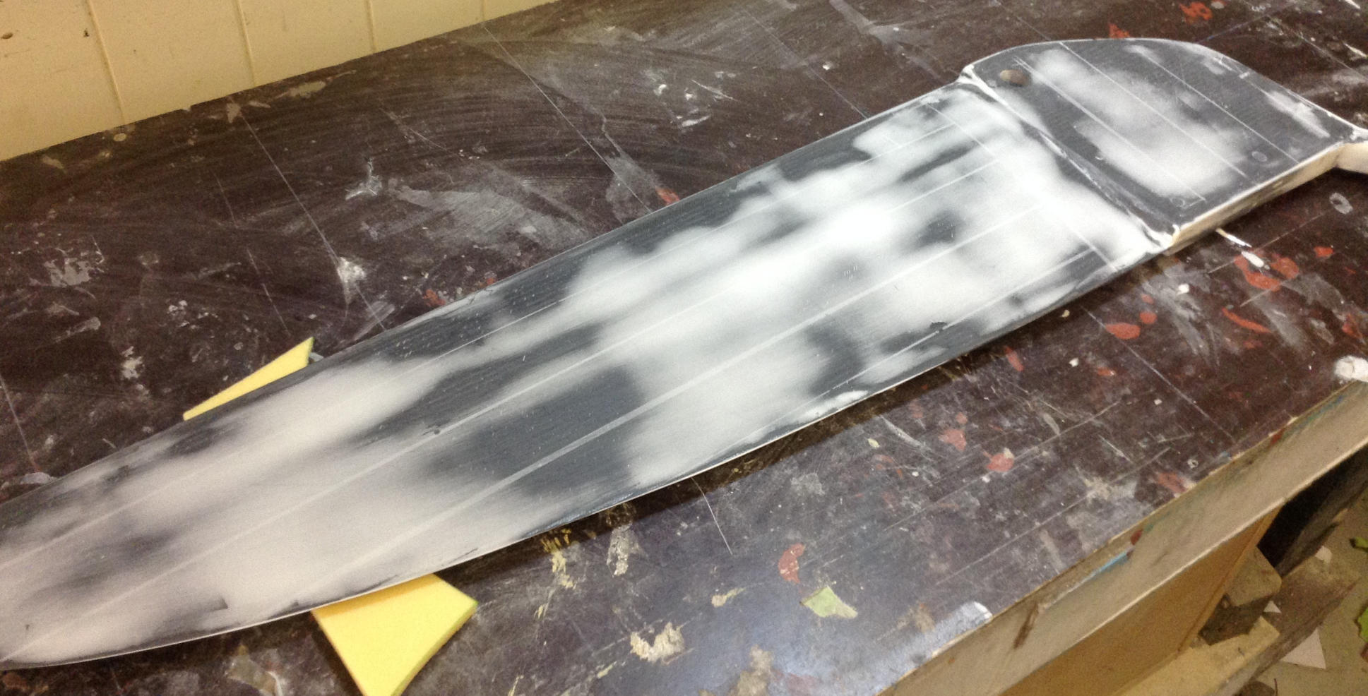
Prior to filling the weave I first used thickened epoxy to fill and faired any imperfections, this included fairing the laminate that wrapped around from the hull to the deck.
The carbon fibre weave was then filled using high build epoxy surfacer which was applied with a squeegee. While this product is quite messy to apply is does sand really easily. I found a single pass with the squeegee worked best, without trying to smooth off the lumps and bumps too much. Figure 70 shows the surface after applying the surfacer but prior to sanding. Figure 70 shows the board after filling and fairing.
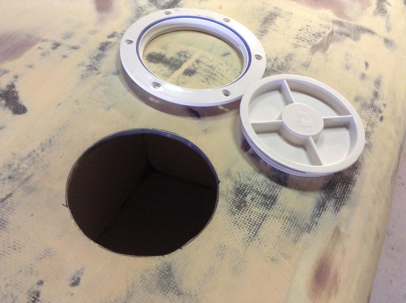
Inspection port
The hole for the inspection port was cut out. Firstly the cut line was marked out. Then using a \(50\,\)mm hole saw sections along the circumference were cut out. Finally using a hacksaw blade the intermediate sections were cut out. The final hole is shown in Figure 72 and has a diameter of \(110\,\)mm.


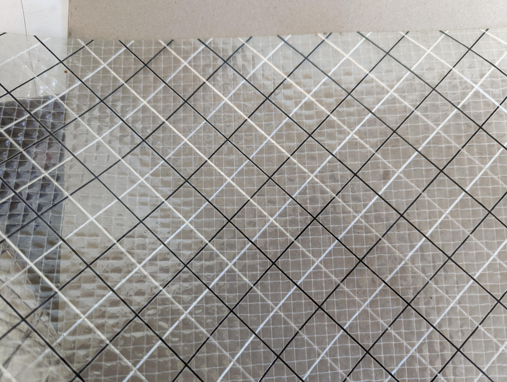
Centre-box gaskets
The gasket was made from fibre reinforced Mylar sailcloth (typical of the cloth used in windsurfer sails), Figure 73. The sail cloth was folded into \(25\,\)mm wide strips. A \(10\,\)mm wide strip of fibreglass tape was then sewed onto one side of the strips using a sewing machine. The fibreglass strip provides a material which will bond to the board using epoxy.
When building the centre-box box I had already rebated about 1mm to allow for the thickness of the gaskets. The gaskets strips were then glued to the board using epoxy resin and the board was placed inside a vacuum bag to ensure a good quality bond. A small amount of epoxy filler was applied to the leading edge of these strips to help prevent them peeling off, Figure 74.
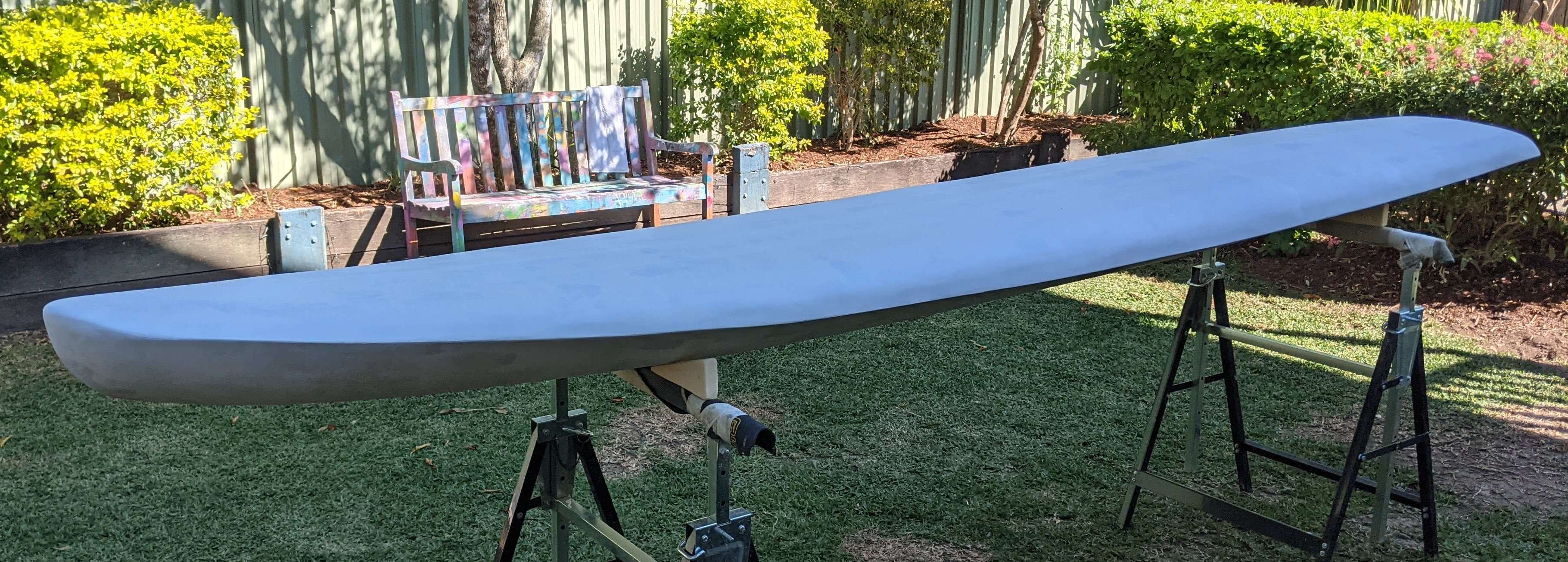
Painting
The painting layup was
Epoxy primer (3 coats)
Two pack polyurethane undercoat (2 coats)
Two pack polyurethane overcoat (3 coats).
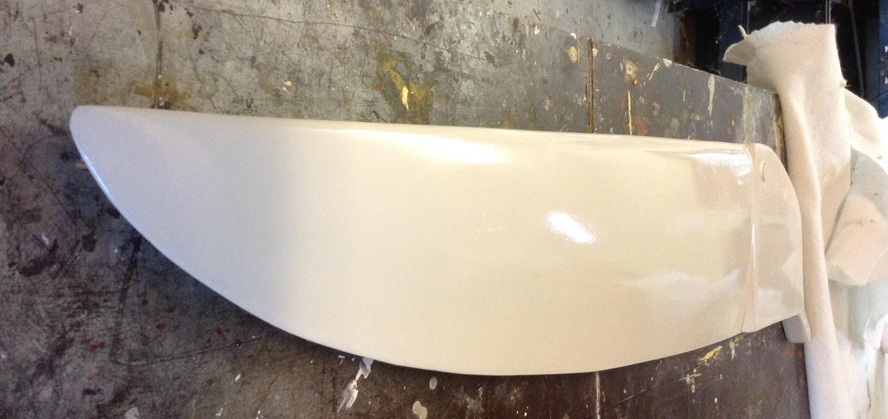
All the painting was done with a roller and a brush. Figure 75 shows the board after the primer was applied and after the final overcoat. Deck grip particles were mixed into the overcoat paint and also sprinkled over the final layer of the deck overcoat.


Centre-board
Centre-board design
The centre-board design is different to the original Lechner centre-board. On the original Lechner the deck slot for the centre-board runs the full length of the centre-board. Further, when the centre-board is retracted the trailing edge of the centre-board sits above the deck, as shown in Figure 76. Instead I designed the centre-board (and box) such that when retracted the centre-board’s trailing edge sits below the deck as shown in Figure 77.
The design of the centre-board can be broken down into a planform and the sections (i.e. cross sectional profiles) and these are defined in Figure 78. The planform can be defined by a leading edge (LE) profile and a trailing edge (TE) profile. At a given location (\(x\)) along the centre-board the distance between the LE and TE is called the chord-length (\(c\)). The location at \(x=0\) is called the root and the location at \(x=L\) is called the tip.
Many studies of sectional profiles for wings and hydrofoils have been published and a well known series are the NACA profiles. These profiles were designed based on results of wind tunnel experiments undertaken in the 1930’s by NACA (National Advisory Committee of Aeronautics, now NASA). Apart from the actual sectional profile an important parameter is the maximum thickness of the section, denoted by \(t\).
The centre-board was designed by first defining the the leading edge such that it followed the rocker profile of of the board when in retracted position, Figure 77. The length of the centre-board was set at \(L=800\,\)mm, this is the length in the water when fully deployed. The chord length at the root was set at \(c_R=205\,\)mm and then the chord lengths at a given location followed an elliptic profile, \[\left(\frac{c}{c_R}\right)^2+\left(\frac{x}{L}\right)^2=1.\] Given the LE profile and the chord lengths then the trailing edge profile can be computed using \[TE=LE+c.\] The planform design is tabulated in file planform_coordinates.xlsx.
For the sectional profile the NACA0012 profile was used, the "12" indicates the maximum thickness of the centre-board at a given location is 12% of the chord-length at that location ("00" indicates no camber, i.e. symmetric section). For example at the root of the centre-board \(c=205\,\)mm so that the thickness of the section at this location is \(24.6\,\)mm. The following equation was used to generate the data points defining the NACA0012 profile \[\frac{z}{c}=\frac{t}{c}\left(b_0\sqrt{\frac{x}{c}}+b_1\frac{x}{c}+b_2\frac{x^2}{c^2}+b_3\frac{x^3}{c^3}+b_4\frac{x^4}{c^4}\right)\] where \(t/c=0.12\) and the \(b\) constants are given in Table 5. Note that the equation above generates a half-profile as shown in Figure 79.


| \(b_0\) | \(b_1\) | \(b_2\) | \(b_3\) | \(b_4\) |
|---|---|---|---|---|
| 1.4845 | -0.63 | -1.758 | 1.4215 | -0.5075 |

Centre-board build
The centre-board was constructed using carbon fibre over a HDF core. The method used follows closely that given in Vacuum Bagging Techniques, section 4.1.2 Laminating a rudder half. The method involves building two negative half-moulds, from which the port and starboard sides of the centre-board are built. The two halves are then glued together.
Positive moulds
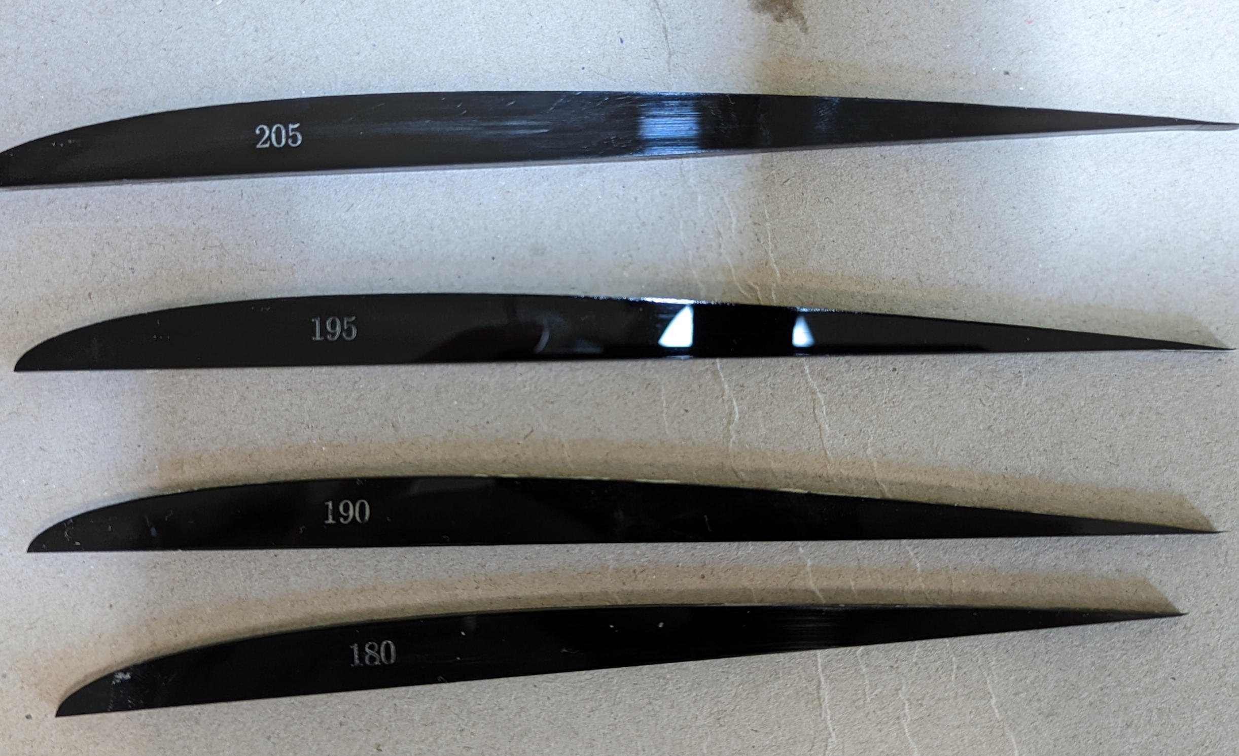
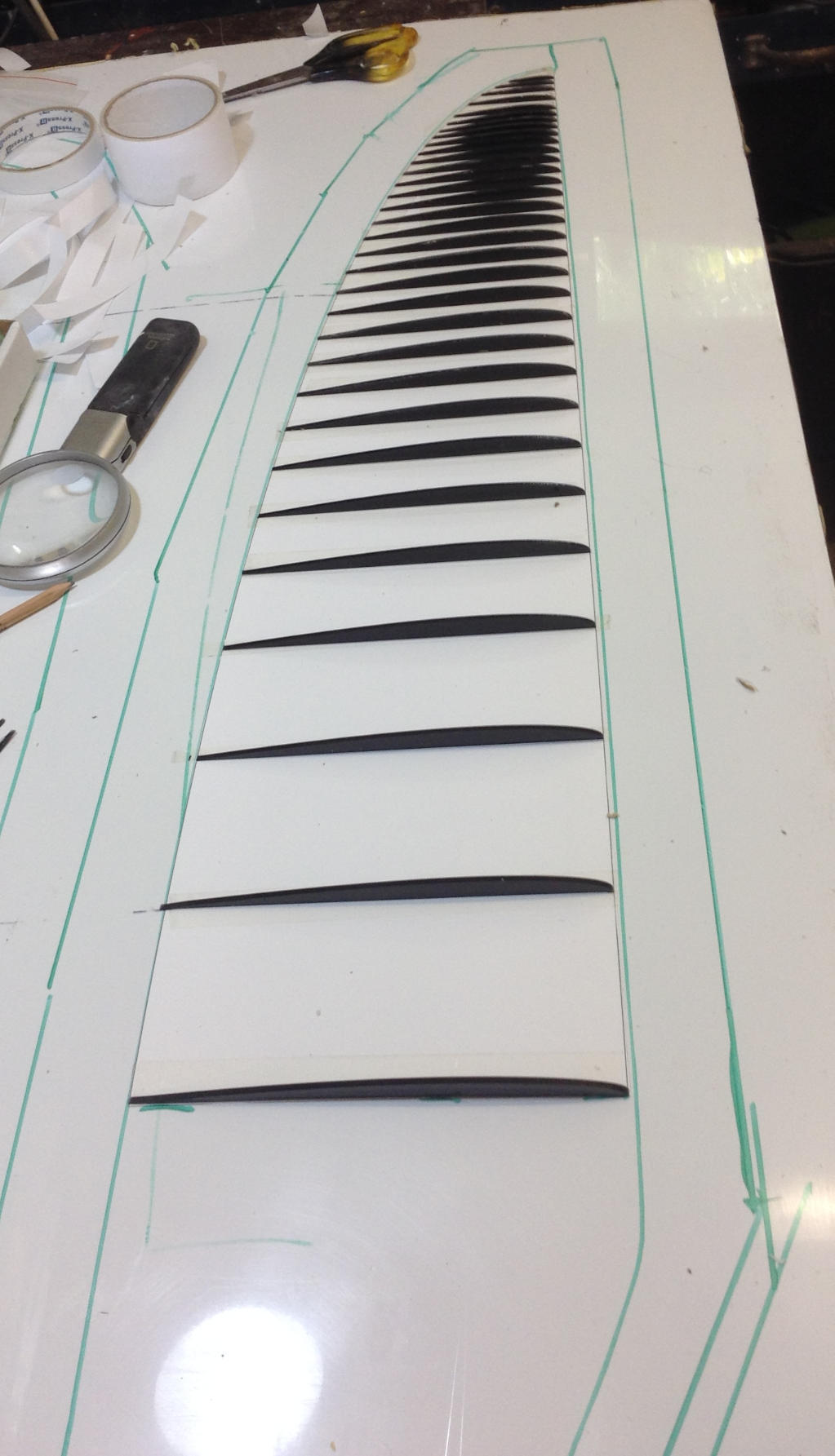
Positive half-moulds were first built. The positive moulds were made from a series of half-section profiles which were laser cut from \(3\,\)mm thick acrylic sheet. The chord lengths of these half-sections varied from \(c=205\,\)mm down to \(c=20\,\)mm, stepping down in \(5\,\)mm increments. Some of these half sections are shown in Figure 80 and these were made by an online laser cutting company.
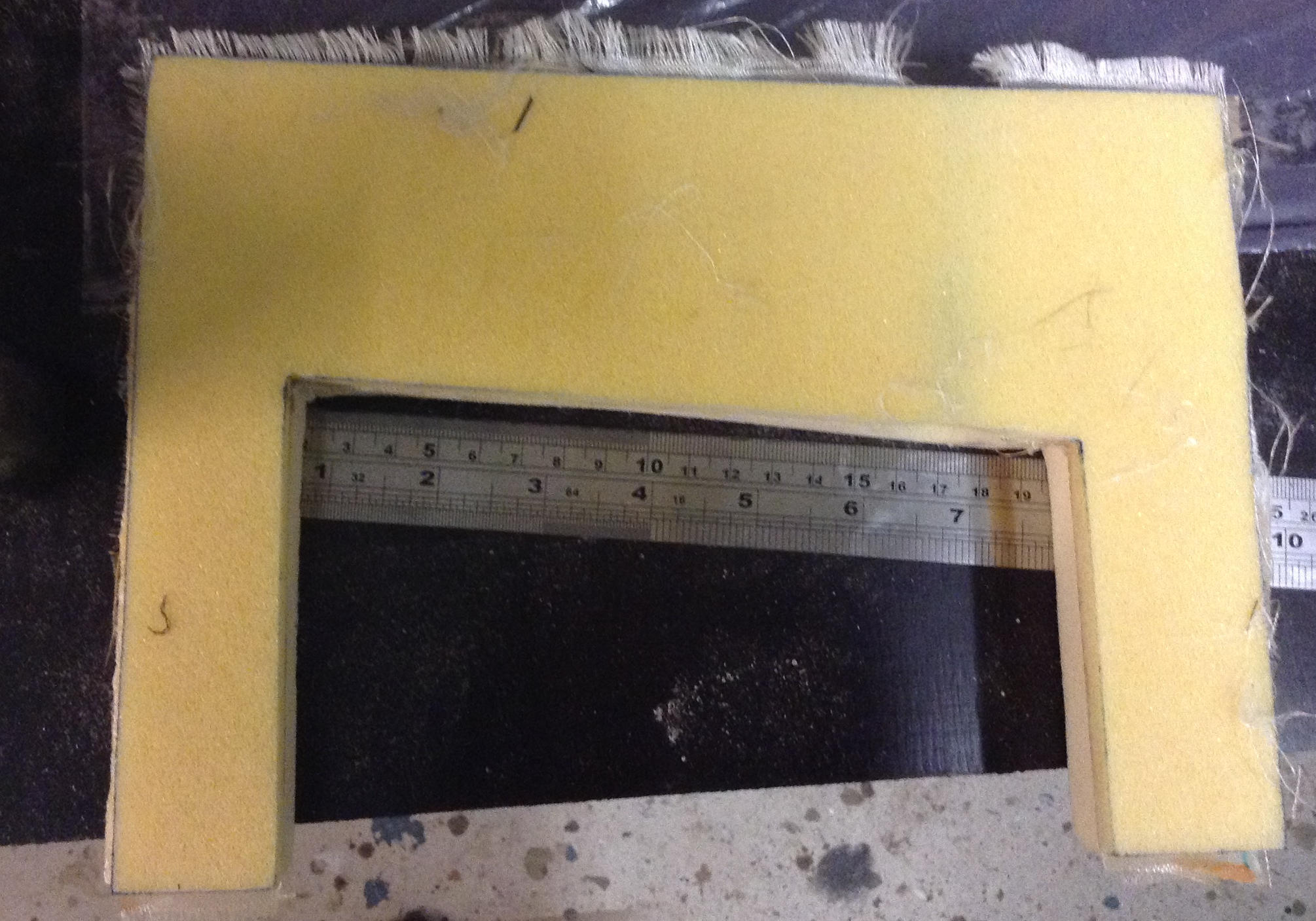
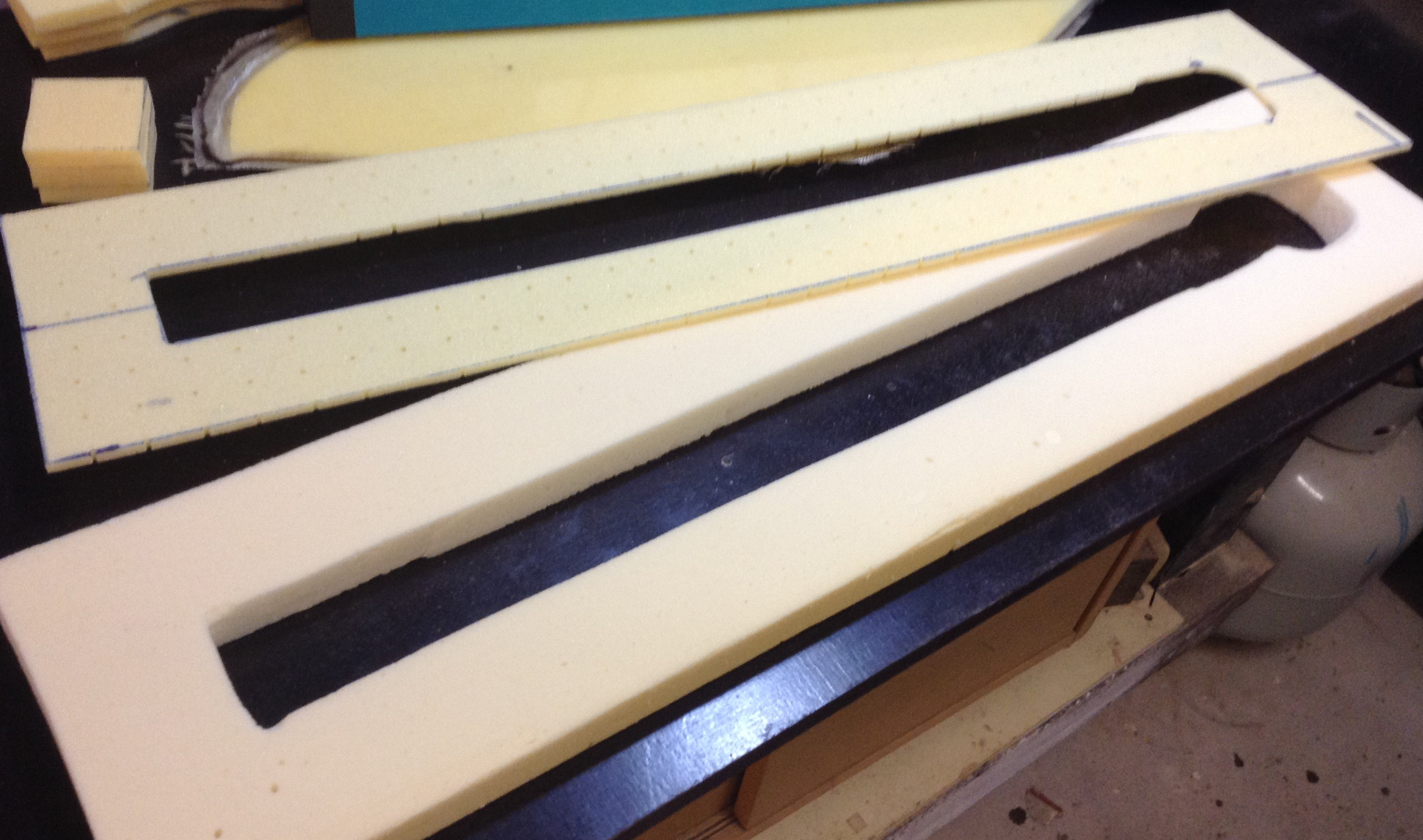
The planform was printed onto an A1 sheet of paper with stations marked for placement of the half sections. A scaled down version of this template is shown Figure 81 and Figure 82 shows the sections placed on the template. Plasticine was then placed between the sections and shaped to the required profiles using the acrylic half sections as guides. I found using a metal paint scraper just wide enough to span two adjacent sections worked well from the shaping of the Plasticine. The mould for the head of the centre-board was made from MDF covered with packing tape. The two positive moulds are shown in Figure 83. A layer of PVA mould release film was applied to the surface of the positive moulds.

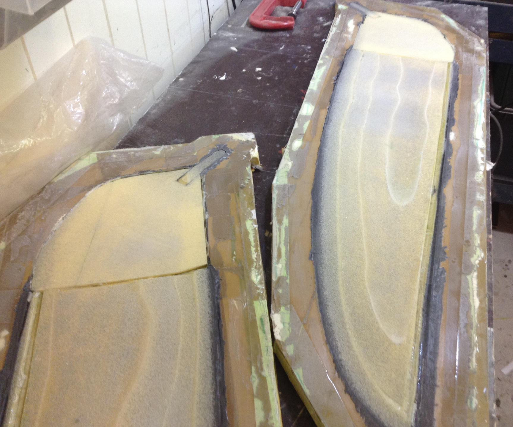
Negative moulds
The negative moulds were made by first applying a layer of thickened epoxy to the positive moulds. Then multiple layers of fibreglass were laminated over the positive moulds. The fibreglass lamination extended beyond the outer edge of the moulds to form a flange approximately \(50\,\)mm wide. A vacuum was applied while the lamination dried. Figure 84 shows the positive moulds covered in fibreglass.
Frames were cut out of \(16\,\)mm thick MDF and these frames were glued onto the fibreglass flange which runs around the edge of the positive moulds. Plaster based filler (Figure 19) was then poured inside the frames such that the plaster was level with the top of the frame faces. The moulds were then sealed with a \(3\,\)mm thick MDF applied on top of the plaster once it had dried. Having built the structure of the negative moulds they could then be lifted off the positive moulds and the completed port-side negative mould is shown in Figure 85. The surface of the moulds were finished by applying packing tape and then release wax, Figure 86.
Layup of centre-board halves
Multiple layers of carbon fibre were laid up in the moulds. The number of carbon layers varied from the head/root region to the tip region, with more layers applied in the high load head/root region. The layup included bi-axial, plain and uni-directional carbon weaves. Unfortunately I did not keep track of the exact lay-up schedule. A layer of \(3\,\)mm HDF was then applied and and the moulds placed inside a vacuum bag, Figure 87.
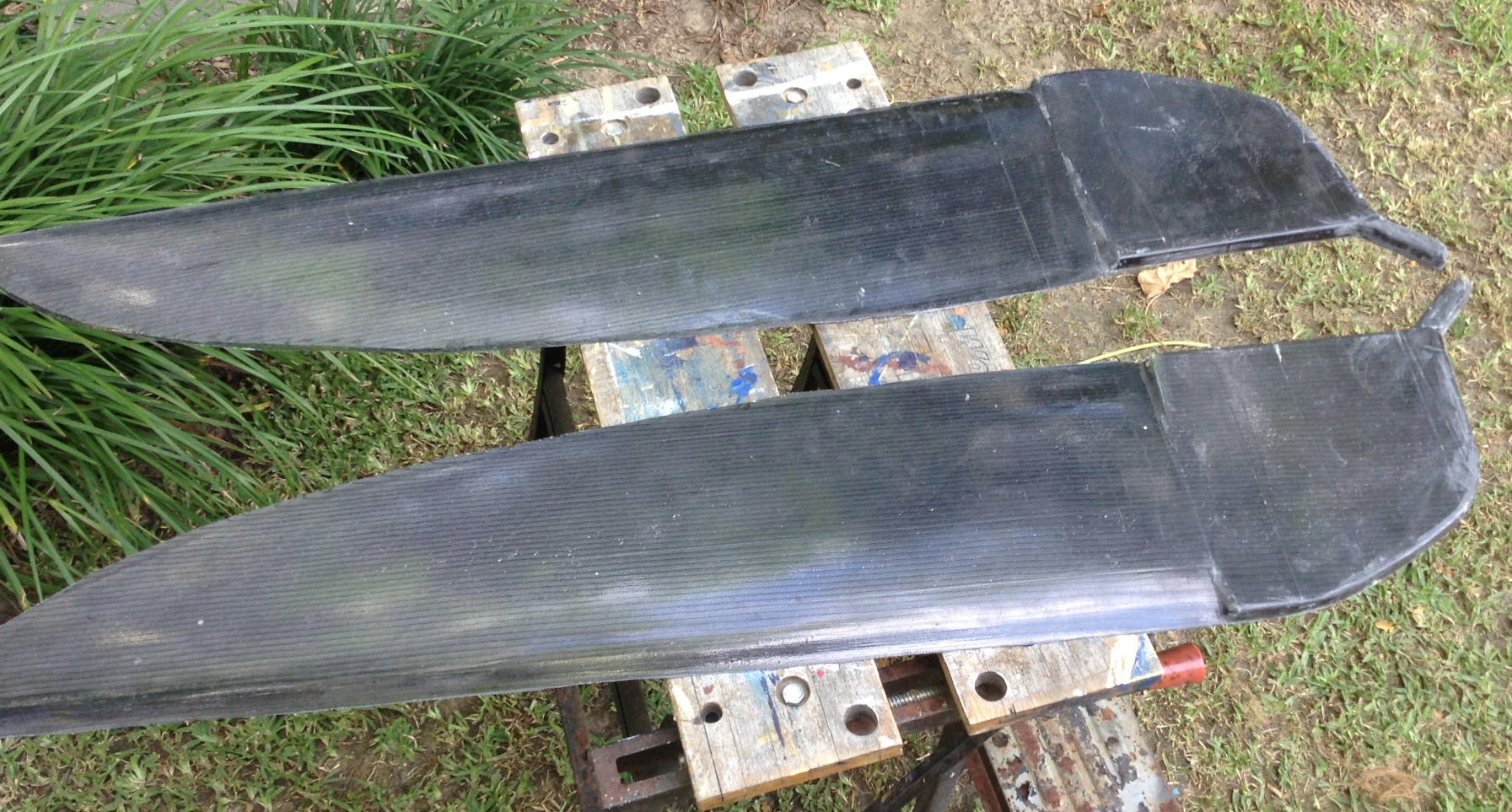
Further layers of HDF were laminated into the moulds to build up the internal core of the centre-board. These HDF layers were then sanded level with the mould flanges, Figure 88. Any gaps in the HDF layers were then filled with thickened epoxy and again sanded level with the mould flanges. The two centre-board halves were then demoulded, Figures 89, 90.
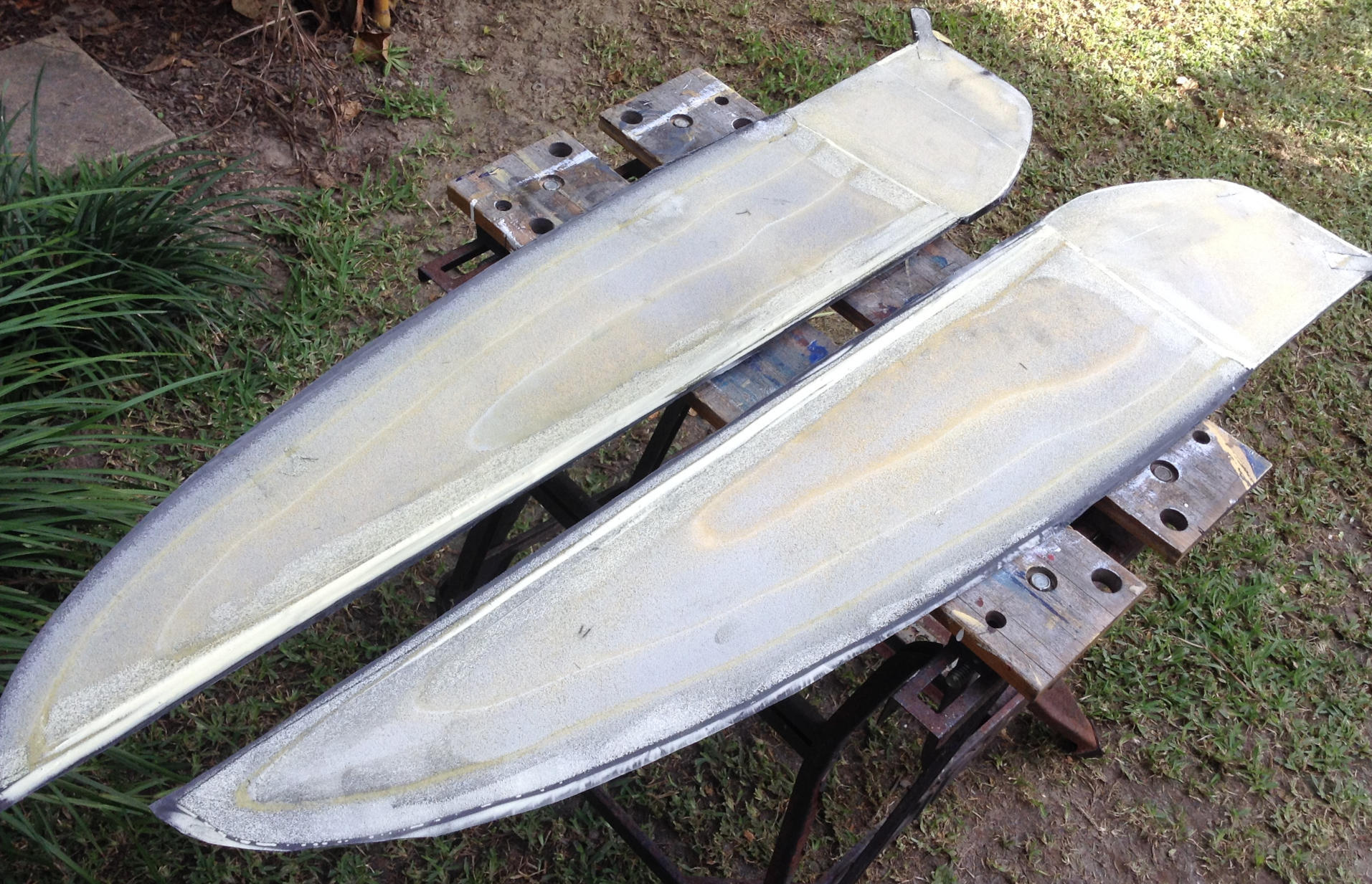
Finishing of centre-board
A fit check of the centre-board in the centre-case was done prior to joining the two halves together. If it is too tight to rotate freely in the case then the core material can be sanded. It is better to have a slightly loose fit and build up the head with filler or fibreglass later if required.
Three dowel pins were made which passed through the centre-board heads. These pins kept the two halves in alignment while they were glued together with thickened epoxy. The centre-board was placed inside a vacuum bag while the glue between the two halves was drying, Figure 91. The hole to house the pivot pin was drilled through the centre-board head. A length of \(20\,\)mm diameter plastic rod was used as the pivot pin and was glued into the hole.
A light layer of thickened epoxy was applied to the centre-board and sanded smooth. The centre-board was then painted using the same paint schedule use for the board and given in the section on painting the board. The finished centre-board is shown in Figure 93.
Centre-board pivot guides
The position of centre-board pivot point is shown in Figure 77. When rotating the centre-board a component of force is directed upwards and there is a tendency for the centre-board to rise up in the guide slots (Figure 37). To restrain the centre-board pivot point at the bottom of the slots “centre-board pivot guides” were made, Figure 94. These are shown fitted to the board in Figure 99.

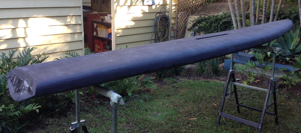
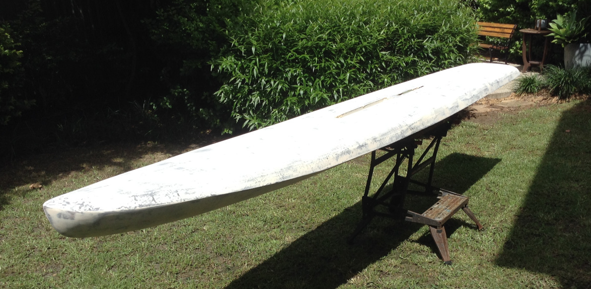
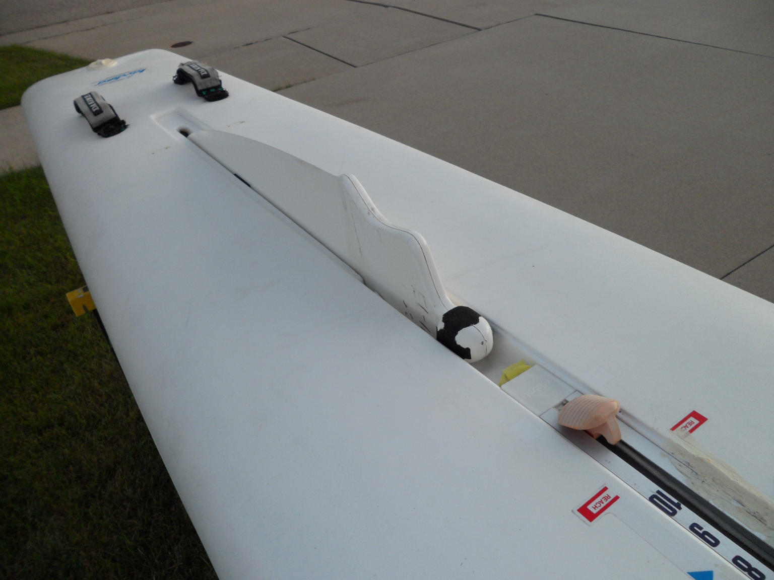
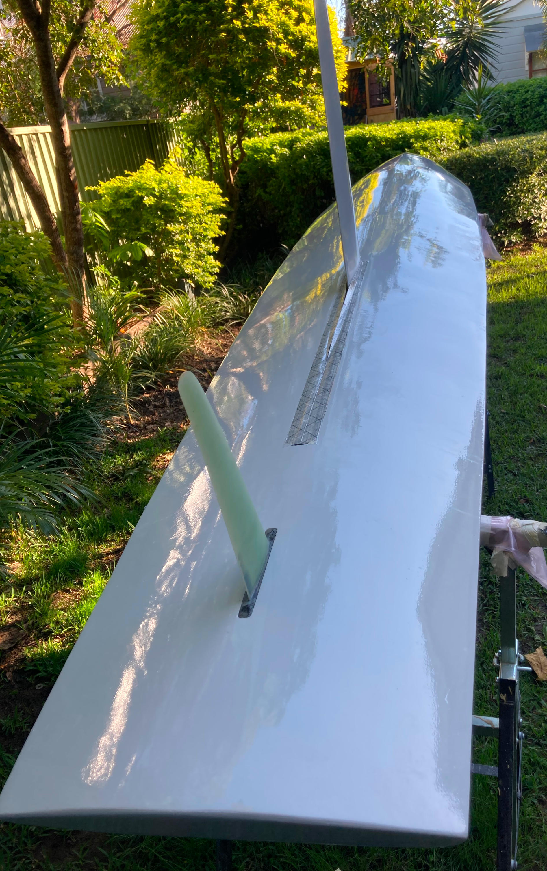
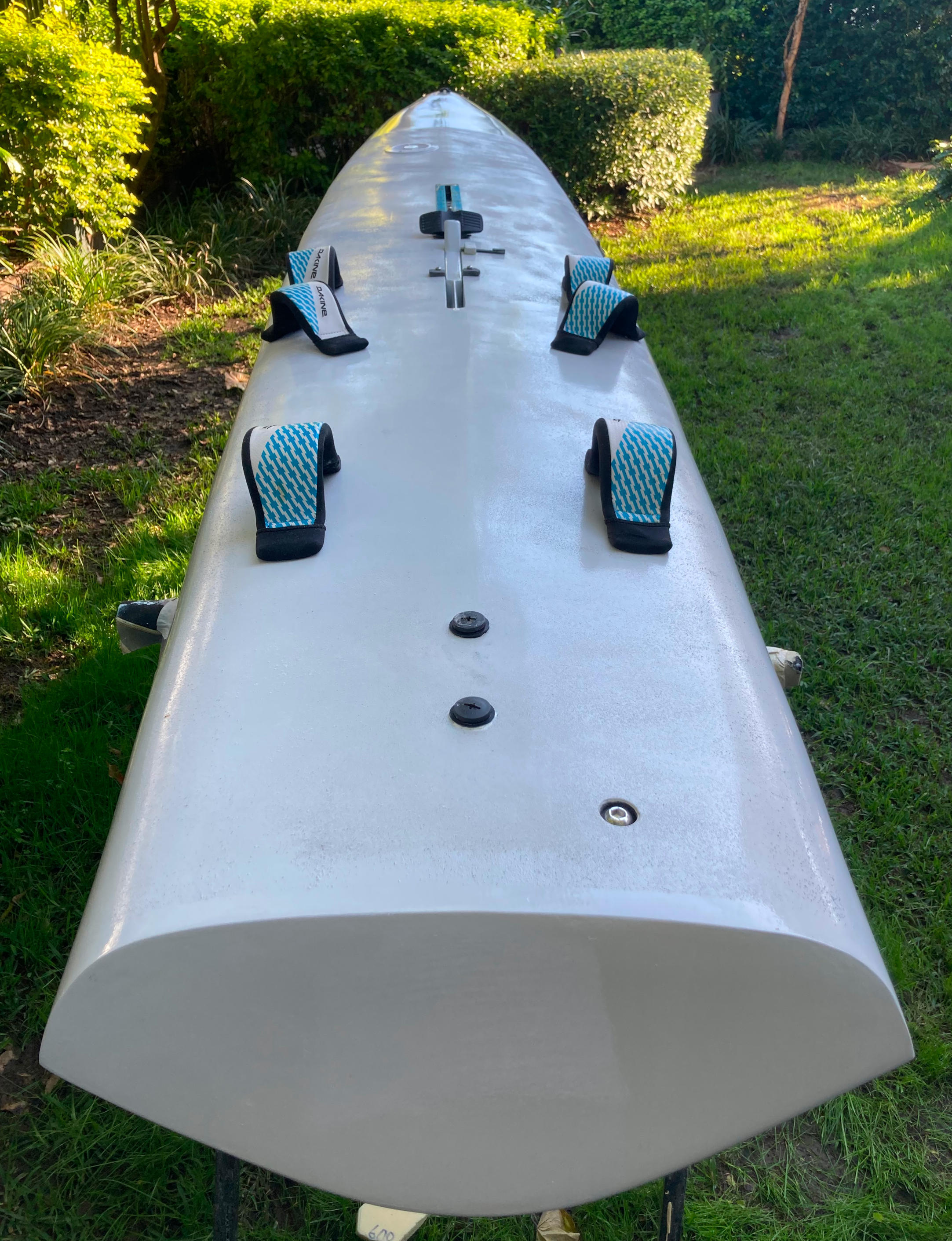
Completed board
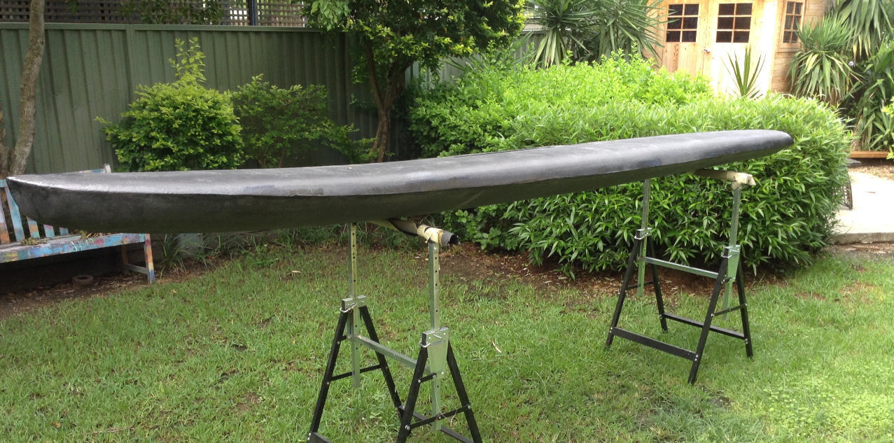
Photos of finished board
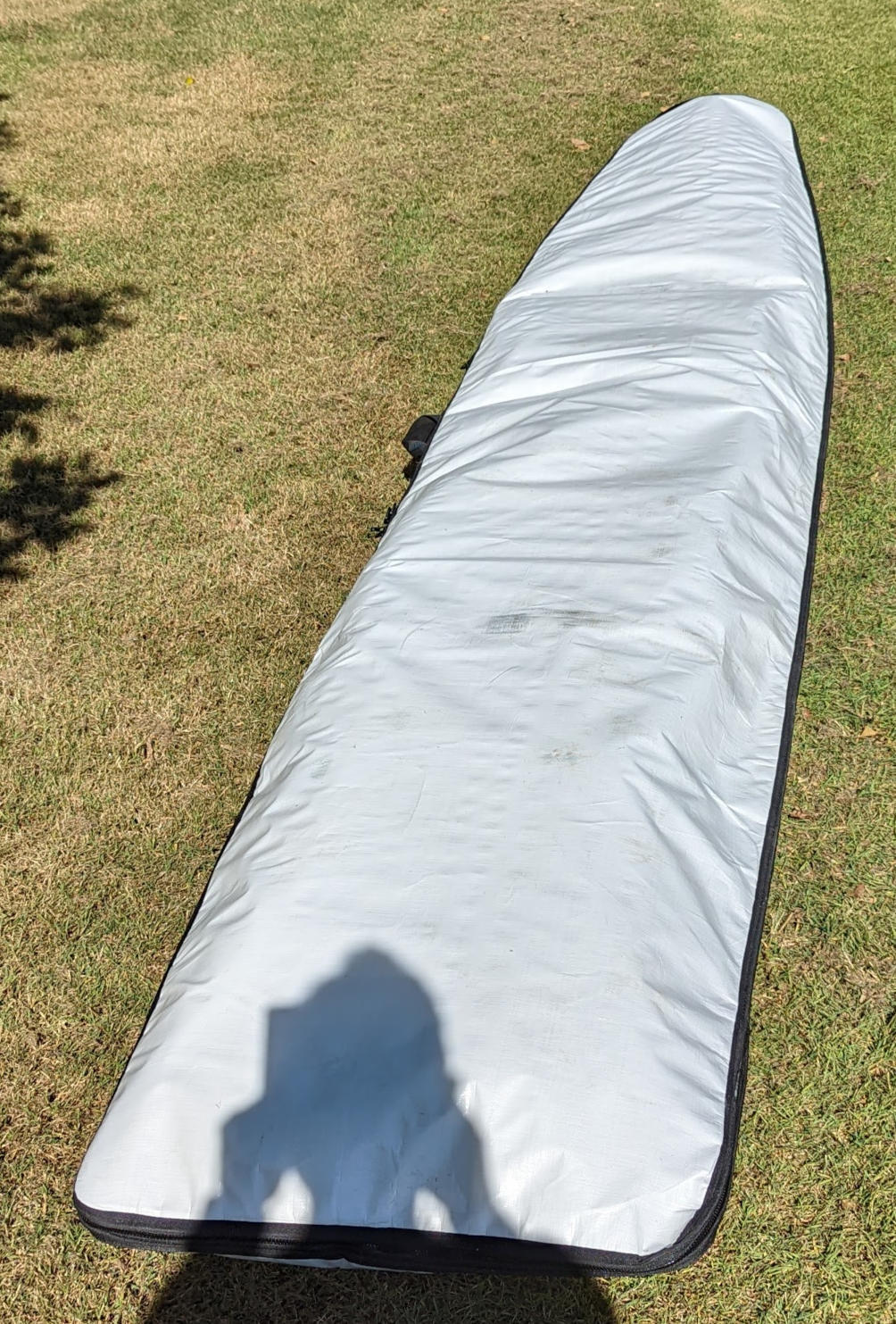
Figure 95-99 show photos of the completed board. I got a board bag custom made to fit, Figure 100.


Testing the board
Structurally the board seems very stiff and I cannot detect any deflection of the skins when pushing hard with my thumb or when standing on the deck. The board is air tight and holds either a positive or a negative pressure depending on the temperature. I find using the inspection hatch is quickest way to equalise the pressure. Although, if a significant pressure difference has built up then the inspection hatch can be difficult to undo and the pressure needs to be equalised using the vent screw first.
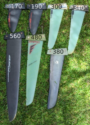
According to this www.seabreeze.com.au post, the original Lechner A390 fin was \(230\,\)mm long and was increased to \(280\,\)mm for the 1992 Olympics. The finbox is standard tuttle and I have a range of fins from \(190\,\)mm to \(560\,\)mm in length, Figure 101. I have mostly used the \(300\,\)mm fin, which seems to work well and it does not feel under finned. I’ve briefly tried going smaller with the \(190\,\)mm fin but found the board very hard to steer when the centre-board was retracted. However, this was in very light winds (\(<5\,\)knots) so may just been lack of board speed.
I am using a \(7.5\,\)m\(^2\) Ezzy Lion, which is a 7 batten, twin cam, freeride sail. It works quite well but would be interested to try a softer freeride sail such as a Hot Sails Maui - Superfreak. Size wise I’ve also tried \(8.5\,\)m\(^2\) Ezzy Infinity (older version of Lion) but found that in light fluky winds the large size and weight of the rig an overall hindrance. This is all for cruising sailing, not racing where outright speed would be the priority. For comparison the 1988 Lechner A390 had an old style Dacron \(6.7\,\)m\(^2\) sail with leech battens only, whereas the 1992 sail was \(7.3\,\)m\(^2\) Neil Pryde fully battened with camber inducers.
So far I’ve used the board in wind ranging from 5-18 knots on flat-water lakes to choppy exposed bays. It feels very comfortable and efficient going to windward. In stronger winds I put my rear foot in the beating strap when going to windward. When powered up off the wind (\(> 15\) knots) it works well with centre board fully retracted, mast track fully back and with front foot in the front planing strap. I’ve only done a few reaches with both feet in the planing straps and I’m not sure if the short board planing stance is the most comfortable.
In powered up choppy waters tacking is definitely easier than gybing and I still need to develop an effective gybe technique. There is still a lot to learn about sailing this board but overall it is not as difficult to sail as I was led to believe from forum posts. However, I would never try and teach someone to windsurf using this board.
Board weight
The weight of the board is \(16.9\,\)kg, measured without footstraps, centre-board or fin fitted. This is about \(1.5\,\)kg more than the estimated value I had calculated prior to building.
Weight of composite sandwich panels
The predicted weight of the composite sandwich panels was estimated by first calculating the surface area of the skins and frames. Knowing the density of the foam, carbon fibre weight in g/m\(^2\) and quantity of resin required to wet out the fibre, the weight of the sandwich panels could be estimated.
The tricky bit was estimating amount of resin required to wet out the fibre. This old catalogue for fibre reinforcements provides some good data the ratio of fibre weight to resin weight. While the ratio depends on the type of fibre and weave, generally for woven fibreglass the ratio is 50:50 and for woven carbon it is 40:60, where the ratio is by weight fibre:resin. For example, the carbon fibre plain weave with a weight of \(198\,\)g/m\(^2\) (F02338) would require \(1.5\times 198=297\,\)g of resin per m\(^2\) of cloth. So my general rule of thumb for carbon is to use 1.5 times weight of cloth of epoxy and when using glass use 1.0 times weight of cloth of epoxy. I always use scales when mixing epoxy so it is easy to weigh cloth first. For larger laminations I’ll calculate the cloth weight based on the area times by the cloth g/m\(^2\) value. For the \(150\,\)g/m\(^2\) biaxial weave carbon I found I needed more than 1.5 factor of epoxy to be confident it was fully wetting it out, whereas for the \(200\,\)g/m\(^2\) plain weave carbon is was getting closer to the 1.5 ratio.
Assuming the above resin to fibre ratios of 1.5 for carbon and 1.0 for glass gives estimated weights of: \(6.4\,\)kg for the skins (no filler or paint) and \(1.5\,\)kg for the bulkheads, see Tables 6 and 7 for detailed breakdown. The front stringer was calculated to have a weight of \(540\,\)g and the chine strips estimated to weight \(500\,\)g. Hence, skin on frame sandwich panels all up were estimated to weigh \(8.94\,\)kg (excluding all the glue).
| Area | fibre | resin:fibre | ||
| m2 | g/m2 | ratio (g/g) | ||
| hull | 2.294 | 150 | 1.5 | |
| deck | 2.364 | 200 | 1.5 | |
| total | 4.658 | |||
| fibre | foam | resin | total | |
| kg | kg | kg | kg | |
| hull | 0.69 | 0.97 | 1.03 | 2.85 |
| deck | 0.94 | 1.00 | 1.42 | 3.57 |
| total | 1.63 | 1.98 | 2.45 | 6.41 |
| x | Area | fibre | resin:fibre | |
| (m) | m2 | g/m2 | ratio (g/g) | |
| 0 | 0.059 | 150 | 1.5 | |
| 0.24 | 0.059 | 150 | 1.5 | |
| 0.35 | 0.063 | 150 | 1.5 | |
| 0.62 | 0.072 | 86 | 1 | |
| 0.83 | 0.078 | 86 | 1 | |
| 1.05 | 0.084 | 150 | 1.5 | |
| 1.3 | 0.090 | 150 | 1.5 | |
| 1.45 | 0.093 | 150 | 1.5 | |
| 1.7 | 0.096 | 86 | 1 | |
| 1.95 | 0.097 | 86 | 1 | |
| 2.2 | 0.096 | 86 | 1 | |
| 2.45 | 0.093 | 86 | 1 | |
| 2.7 | 0.089 | 86 | 1 | |
| 2.95 | 0.082 | 86 | 1 | |
| 3.2 | 0.071 | 86 | 1 | |
| 3.45 | 0.056 | 86 | 1 | |
| 3.7 | 0.032 | 86 | 1 | |
| Total | 1.311 | |||
| x | fibre | foam | resin | total |
| (m) | g | g | g | g |
| 0 | 17.8 | 38.6 | 26.8 | 83.2 |
| 0.24 | 17.8 | 38.6 | 26.8 | 83.2 |
| 0.35 | 18.9 | 41.0 | 28.4 | 88.4 |
| 0.62 | 11.5 | 46.9 | 11.5 | 71.7 |
| 0.83 | 12.5 | 50.8 | 12.5 | 77.7 |
| 1.05 | 25.2 | 54.7 | 37.9 | 117.8 |
| 1.3 | 27.1 | 58.7 | 40.6 | 126.3 |
| 1.45 | 27.9 | 60.5 | 41.9 | 130.4 |
| 1.7 | 15.4 | 62.5 | 15.4 | 95.5 |
| 1.95 | 15.5 | 62.9 | 15.5 | 96.2 |
| 2.2 | 15.3 | 62.1 | 15.3 | 95.0 |
| 2.45 | 14.9 | 60.4 | 14.9 | 92.4 |
| 2.7 | 14.2 | 57.7 | 14.2 | 88.2 |
| 2.95 | 13.2 | 53.5 | 13.2 | 81.8 |
| 3.2 | 11.3 | 46.1 | 11.3 | 70.5 |
| 3.45 | 8.9 | 36.2 | 8.9 | 55.3 |
| 3.7 | 5.1 | 20.6 | 5.1 | 31.5 |
| Total | 273 | 852 | 340 | 1485 |
Weight of all components
The weight of all components is summarised in Table 8 and most of the values are estimates based on the layup with an assumed resin to fibre ratio. Some parts I did weigh, such as the finbox and mast-track. The actual as-built board weighs \(16.9\,\)kg, so there is about \(1.3\,\)kg unaccounted for. I suspect I used more resin, glue and filler than estimated in Table 8. There may also be more weight in paint, given that there was a total of 8 coats of paint.
| Component | kg |
| skin | 6.4 |
| bulkheads | 1.5 |
| stringer | 0.5 |
| chine | 0.5 |
| mast-track & box | 1.2 |
| centre-box | 1.2 |
| fin-box | 0.6 |
| footstrap-plugs | 0.3 |
| reinforcements | 0.5 |
| glue | 1 (1.5) |
| filler | 0.6 (1.0) |
| paint | 0.75 (1.0) |
| extra resin | 0.5 (0.65) |
| Total | 15.6 (16.9) |
Weight savings
Based on the above weight budget, I think you could reduce the weight by at most \(1.5\,\)kg but still employ the same skin on frame technique with the same layup and number of bulkheads. These weight saving would need to come from following:
Fin-box, centre-box and masttrack-box. Reduction in number of laminations used in these fittings.
Less filler to fair imperfections in the deck and hull. More precise board mould.
Less glue when joining components.
Less paint.
Less resin rich layups.
The question is by how much the above could be reduced without compromising the integrity of the board? To reduce weight more substantially would require removing the number of bulkheads and perhaps the front stringer. This would require a fundamental change to the method of manufacture and the skins would need to be fully moulded on the mould (i.e. outer lamination done when skins still on the mould). Using only the chine strip the two halves would then be glued together. Removal of the bulkheads would reduce weight by around \(1.5\,\)kg.
Vacuum pump and controller
Vacuum bagging is often used as a method to clamp and consolidate composite laminates. It is particularly useful for fibre sandwich composite where the vacuum bag provides a force that bends and holds the foam core to the required shape as the resin cures. A good guide to the technique is give in the West Systems Vacuum Bagging Techniques document.
A vacuum pump is used to create the required vacuum. Running the vacuum pump continually may create too strong a vacuum which may crush the core or cause resin starved components. In order to control the vacuum I built an electronic controller that is designed to switch off the pump once a certain low pressure is reached. When the pressure rises back up to a certain level the controller then switches the pump back on.
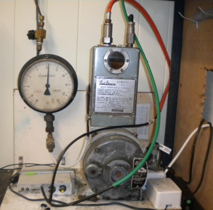
Vacuum pump
This system uses a Rud Browne, DynaVac 1 single stage rotary vane vacuum pump, Figure 102. These were an Australian made pump but it seems the company is no longer in business. The name plate quotes a pumping speed of \(30\,\ell\)/min at \(760\,\)mmHg (i.e. at no load) and a pumping speed of \(0.3\,\ell\)/s at \(0.1\,\)mmHg (i.e. at full load). The name plate also quotes an ultimate vacuum of \(0.005\,\)mmHg (i.e. \(0.6\,\)Pa or \(99.999\,\)% vacuum).
Vacuum contoller
The circuit diagram for the vacuum controller is shown in Figure 104. The main components are a differential pressure transducer, a difference amplifier, a micro-processor, and a transistor driving a relay switch.
The pressure transducer is a strain gauge device that outputs a voltage difference, \(\Delta V=V_2-V_1\), which is proportional to the applied pressure (or vacuum). The pressure transducer is a differential unit, that is it measures the pressure difference between port ’A’ (high pressure) and port ’B’ (low pressure). Port ’A’ is left unconnected (i.e. vented to atmosphere) whereas port ’B’ is connected to the vacuum line. This creates a positive pressure difference on the sensor as the vacuum draws down. The sensor has a maximum range of \(15\,\)PSI and at full scale gives an output of \(\Delta V=250\,\)mV.
The sensor output voltage is amplified using a differential amplifier (part no. INA103). The gain on this amplifier is set using resistor \(R_G\approx 320\,\Omega\) and this gives an amplifier gain of \(G=20\). The output of the amplifier is then in the range \(0\) to \(5\,\)V (full scale). This voltage is sampled by the Arduino on the pin labelled “analog in 1” (\(A1\)) on Figure 104. The Arduino also samples two other reference voltages on “analog in 2” (\(A2\)) and “analog in 3” (\(A3\)). The microprocessor compares the sensor voltage A1 to the reference values \(A2\) and \(A3\). If \(A1<A2\) the pump will turn on then when \(A1>A3\) the pump turns off. The voltage \(A2\) and \(A3\) are adjusted by turning knobs on the controller front panel. Hence, the desired turn-on and turn-off vacuum pressure levels can be set. Importantly the difference between the values of \(A2\) and \(A3\) can be used to generate a hysteresis effect so the the pump does not “hunt” on-off/on-off.
The actual switching of the pump is initiated via the low current trigger signal sent out of the Arduino. When this signal is at \(5\,\)V the transistor (part no. BD681) switches on and current passes through the relay coil from the \(12\,\)V power supply, switching the mechanical relay and hence the compressor on.
Invariably there will be small leaks in the bag. The effect of these leaks on the vacuum level can be greatly reduced by placing a vacuum “reservoir” in the circuit, to achieve this I used a \(9\,\)kg gas bottle. With a well sealed bag and a vacuum reservoir the pump would switch on for about \(1\,\)min. each half hour or so.


Hot-box
The epoxy resin I used was Gurit Ampreg 31 with slow hardener. The data sheet curing schedule states that good mechanical properties are achieved after an ambient temperature only cure. However, the data-sheet goes on to say “Post curing the laminate will greatly increase mechanical/thermal properties. The system will achieve similar properties with a cure of 5 hours at 70 - 80\(^\circ\)C or 16 hours at 50\(^\circ\)C. ”
For the post curing I built a hot-box from \(3\,\)mm MDF sheets, Figure 105. I had an old oven element which had an electrical resistance of \(60\,\Omega\), which connected to \(240\,\)V AC, should equate to \(960\,\)Watts of power. I also placed a small fan from an old computer power supply inside the hot-box to help convect the heat uniformly throughout the hot-box.
I used DS18B20 1-Wire thermometers to measure the temperature at two locations inside the hot-box, one near the heating element and the other at the far end. Note these thermometers need additional hardware to read the output and I used a 1-Wire COM Port Adapter connected to my PC through a COM port to USB cable. Alternatively a Raspberry Pi or Arduino could be used to read the thermometer.
Several layers of insulating material were required to be added to the outside of the hot-box to obtain a temperature of 50- 60\(^\circ\)C. I found the cheapest option was just to grab a heap of doonas (luckily it was middle of summer, so no one missed their doona). According to the data-sheet it is important that the ramp up rate is within the recommended 10\(^\circ\)C/hour. However, thermostat control of heating element was not required and with the heating element always on, the hot-box came to an equilibrium of around 55\(^\circ\)C after about 3 hours. The hot-box was then held at this temperature for around 16 hours and the after switching off the heating element it took about 2 hours to cool back down to ambient temperature.
Construction techniques
Internal frame versus foam core
The board was constructed using a skin on frame technique which eliminates the internal foam core typically used in windsurfers. It appears many of the Division-2 boards were constructed this way. A hollow board has certain advantages compared to a foam cored board.
Shaping a polystyrene block requires skilled craftsmanship. For the one off or occasional board building I believe an internal shape offers more accurate control over the shape. This is because you only ever need to cut 2-dimensional panels, which when connected form the underlying 3-dimensional shape. Related to this is that more complex and highly curved shapes of the Lechner would be easier to accurately achieve with less skill.
Less likely to deform during the vacuum bagging process. The internal frame provides an inherently more rigid core than the polystyrene and hence, should resist deformation without having to built a rocker table.
Any water ingress to the core can be easily deal with. With my previous board there was a small manufacturing defect within the centre-board housing that allowed water to slowly enter. I’ve also had experiences where small cracks in fin-boxes and around footstrap screws have led to water ingress. Once this has happened it is very difficult to get the weight back to the original.
Internal storage. I included a \(100\,\)mm diameter inspection port in the deck and hence can carry things such a water bottle inside the hull.
The frame offers a far stiffer structure than a polystyrene foam core of the same weight. Although with boards of this thickness (up to \(200\,\)mm thick) overall board stiffness is not really an issue as there is sufficient overall stiffness from the skins alone.
It is interesting to compare the weight of an equivalent built board but using a polystyrene foam core instead. The volume of the board is \(330\,\ell\) and the lightest density polystyrene foam is around \(14\,\)kg/m\(^3\), so that the foam core would \(4.62\,\)kg. From Table 8 the weight of the internal frame, including all the glue, is somewhere between \(3.5\) to \(4\,\)kg. So maybe at best the internal framed method I used saves about \(1\,\)kg compared to polystyrene foam core equivalent.